Transcription of Fifth Wheel Hitch 30866 - reeseprod.com
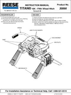
1 INSTRUCTION MANUAL Product No. You can take it with you. TITAN 16K - Fifth Wheel Hitch 30866 . Plymouth MI. DEALER/INSTALLER: END USER: (1) Provide this Manual to end user. (1) Read and follow this Manual every time you use Hitch . (2) Physically demonstrate hitching and unhitching (2) Save this Manual for future reference. procedures in this Manual to end user. (3) Pass on copies of Manual to any other user or owner of Hitch . (3) Have end user demonstrate that he/she (4) Never remove Hitch warning decals as shown on the cover of this understands procedures. manual. If damaged, contact Reese (1-888-521-0510 or ) . HANDLE. JAWS TO HOLD KINGPIN. HEAD ASSEMBLY. RAMP. SKID PLATE. SIDE BRACKETS. For Installation Assistance or Technical Help, Call 1-888-521-0510. 30866IN_G 15 MAY17 PCN9757 2012, 2017 HORIZON GLOBAL LITHO IN CHINA. WARNING: Failure to follow these instructions may result in death or serious injury! INDEX. 1. GUIDELINES FOR MATCHING TOW vehicle AND TRAILER P. 2.
2 2. ASSEMBLY INSTRUCTIONS P. 4. 3. BEFORE EACH TRIP P. 5. 4. HITCHING PROCEDURE P. 5. 5. PULL TEST P. 8. 6. UNHITCHING PROCEDURE P. 8. 7. MAINTENANCE P. 9. 8. REESE LIMITED LIFETIME WARRANTY P. 9. GUIDELINES FOR MATCHING Hitch TRUCK AND TRAILER. WARNING: Trailer and its contents together must not exceed truck, Hitch and/or trailer tow ratings. Towing vehicle must have a manufacturer's rated towing capacity equal to or greater than the gross trailer weight (dry weight of the trailer plus payload of the trailer). (See Fig. 1). Gross weight of trailer must not exceed 16,000 pounds. King pin weight must not exceed 4,000 pounds (See Fig. 2). If in doubt have king pin weight measured by qualified facility. Fig. 1. FACTORY TRAILER + FULL WATER TANKS + CARGO, ETC. = GROSS TRAILER WEIGHT. 1. Reese hitches are designed for use with recreational Fifth Wheel trailers only, do not exceed vehicle tow rating capacities. 2. Use only a SAE 2-inch king pin with your Reese Fifth Wheel Hitch .
3 3. Approximately 15%-25% of trailer weight should be on Hitch (Pin Weight). See Fig 2. Fig. 2. 15-25%. GROSS TRAILER 75-85%. WEIGHT GROSS TRAILER. (PIN WEIGHT) WEIGHT. GROSS TRAILER WEIGHT. 30866IN_G 15 MAY17 PCN9757 2012, 2017 HORIZON GLOBAL LITHO IN CHINA. 4. Trucks come in many different configurations. Reese hitches are designed for use in light trucks such as the Ford F- Series, the Chevy Silverado and the Dodge Ram. Reese recommends the use of long bed (8ft) light trucks for the best combination in truck - trailer turning clearance. Rule of thumb: The distance from the back of the truck cab to the center of the rear truck axle ( X in Fig. 3), should be approximately 4 inches greater than one-half the trailer width ( Y in ). RV TRAILER. Fig. 3. TRUCK KING PIN. 5. If a short bed pickup (less than 8 ft. but longer than 5 ft. 6 in.) is to be used for towing, Reese recommends the trailer be equipped with an extended pin box to help gain additional truck - trailer turning clearance (See trailer manufacturer for options) (See Fig.)
4 4). It also may be helpful to add a Reese Slider for increased turning clearance for low speed, non- highway maneuvering (See for applicable short bed solutions). Fig. 4. Conventional Pin Box Extended Pin Box WARNING: DO NOT install this Fifth Wheel Hitch on or attempt to tow with a short bed pickup truck that has a bed shorter than 5 ft. 6 in.! Special mounting systems and careful trailer assessments are critical! 6. The height of the Hitch and the pin box should be adjusted so the trailer is approximately level as it is towed. Allow approximately 6 inches clearance between the top of the pickup walls and the underside of the front of the trailer for pitch and roll of the trailer. (See Fig. 5). Allow more clearance between pickup walls and trailer for off road use. Fig. 5. Approximately 6 Inches Level Trailer . 30866IN_G 15 MAY17 PCN9757 2012, 2017 HORIZON GLOBAL LITHO IN CHINA. WARNING: DO NOT use this Hitch for towing a trailer with a pin box that could come in contact with or interfere with the latch of the Hitch handle when turning!
5 (See Fig 6) If the pin box contacts the Hitch handle or its latch when turning, the trailer may become unhitched. KING PIN. HANDLE. BOTTOM OF PIN BOX. Fig. 6. WARNING: Connection for trailer wiring should be in the side of the truck bed between the driver's seat and the Wheel well for the back truck axle Installation of connection rearward of the Wheel well may result in user placing body between truck and trailer. WHENEVER POSSIBLE, AVOID PUTTING BODY UNDER TRAILER. OR BETWEEN TRUCK AND TRAILER! If you need to place any part of your body under trailer or between truck and trailer: All trailer tires MUST be blocked in front and behind each tire AND. Trailer landing gear MUST be resting on firm ground AND. Truck MUST be stationary, in park, with emergency brake on! ASSEMBLY INSTRUCTIONS. 1. Reference Fig. 21 on back page. Number in parentheses refer to parts in Fig. 21. 2. TITAN 16K Fifth Wheel is contained in two cartons. Unpack and become familiar with parts on parts list.
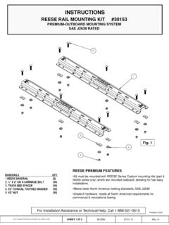
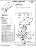
6 Base rail, brackets and hardware are in separate kits with separate installation instructions (sold separately). 3. Place two base rails across bed of truck (See Fig 7). Select one leg and place tabs through the middle rectangular slot in the base rails. Slip long pull pins through holes in base rails from the inside out as shown so the cotter pins are on the outside of the base rails. Repeat for other leg. Secure pull pins with the spring retaining pins . BASERAILS. Fig. 8b Fig. 7 Fig. 8a 4. Select cross member (6) and install on leg aligning holes for Hitch height desired. (Lowest position 14 highest 18 ). Install four Socket Head bolts (8), with the heads towards the outside as shown, and lock nuts (9). 5. Torque nuts to 75 6. Place the pivot beam and head assembly( ) over the cross member (6) and secure with the locking pins (11 ). The locking pins must have the end lock portion turned vertically, centered and snapped in place to ensure proper locking (see Fig 8b).
7 7. Install base rails and mounting brackets as described in Installation Instructions for 5 th Wheel Rail Mounting Kit.. WARNING. Base rails must be bolted through the floor of the pickup to the brackets that attach to the truck frame. DO NOT INSTALL BY FASTENING TO THE FLOOR OF THE PICKUP BOX. ONLY. The floor alone is not strong enough to carry the loads imposed by the trailer. 30866IN_G 15 MAY17 PCN9757 2012, 2017 HORIZON GLOBAL LITHO IN CHINA. BEFORE EACH TRIP: 1. Lubricate skid plate of the Hitch (see figure on cover of Manual) with automotive type chassis grease or use a plastic lube plate to provide a lubricated surface. 2. Plastic lube plates (Reese No. 83002) can be used to avoid messy grease. The plastic lube plate must not exceed 3/16 of an inch in thickness to ensure Hitch will operate properly. Lube plates must be 10 inches in diameter or larger to properly distribute king pin weight. 3. Before each trip or maneuver, operate the handle and check that the jaws open and close freely.
8 4. See that all Hitch pins (#11 on Fig. 20) are in place and are locked in place for attachment to the pivot beam. See that all Hitch pins (#13 on Fig 20) are in place on the mounting system and the spring retaining clips (#10 on Fig 20) are installed. HITCHING PROCEDURE: IMPORTANT: YOU ARE RESPONSIBLE FOR SAFE HITCHING AND UNHITCHING OPERATIONS. DO NOT RELY ON. OTHERS TO PERFORM YOUR DUTIES. YOU MUST PERSONALLY MAKE SURE THE FOLLOWING. STEPS ARE PERFORMED IN THE FOLLOWING ORDER! WARNING: FAILURE TO FOLLOW THESE INSTRUCTIONS MAY RESULT IN DEATH OR SERIOUS INJURY. 1. Place blocks (sometimes called chocks ) firmly against front and rear of each trailer Wheel to prevent any possible forward or rearward motion. DO NOT REMOVE BLOCKS UNTIL EACH OF THE FOLLOWING STEPS AND THE PULL TEST HAVE. BEEN COMPLETED. Lower tailgate if necessary. 2. Rotate Hitch handle from locked position (see Fig 9a ) up to the unlocked position (see Fig 9b). This will unlock the jaw system. NOTE: Hitch jaws will not open and proper hitching cannot occur if handle is not pointed up.
9 LOCKED UNLOCKED. Fig. 9a Fig. 9b 3. Using trailer jacks, adjust trailer height following directions in the trailer manual so that the bottom of trailer pin ( A in Fig 10) is to 1 below skid plate (See B in Fig 10). During the hitching maneuver, the bottom of the trailer pin box should come in contact with the skid plate ramp (See C in Fig 10). It is important the LIFT the trailer so the truck and trailer suspension can align and the king pin enters and locks properly in the jaw system. WARNING: Failure to follow this instruction may result in the king pin being too high and coming to rest on top of the closed jaws or not completely inside jaws (see fig 13). This could result in trailer separating from the Hitch . Trailer separation may result in death or serious injury if anyone is under the trailer or between truck and trailer when separation occurs. 30866IN_G 15 MAY17 PCN9757 2012, 2017 HORIZON GLOBAL LITHO IN CHINA. Bottom of Pin Box Above Hitch Skid Plate (B) Hitch Skid Plate Bottom of Pin Box (A) 1/2 To 1 Inch Below Hitch Skid Plate (B).
10 Bottom of Pin Box (A). Fig. 11. Skid Plate Ramp (C) WRONG. Fig. 10. CORRECT. WARNING: DO NOT ATTEMPT TO Hitch TRUCK AND TRAILER BY LOWERING THE TRAILER INTO THE Fifth Wheel . ASSEMBLY FROM THE TOP. THIS COULD CAUSE A HIGH PIN SITUATION AND THE TRUCK AND TRAILER. WILL NOT BE HOOKED UP (SEE FIG 10 AND FIG 16). Fig. 12. Handle will move out when kingpin makes contact with the jaws Fig. 13. King pin King pin King pin Indicator Out kingpin is Make sure that the handle has moved to the in Locked in position position and that the hole in the head and the hole in the handle tab are aligned; along with the kingpin indicator is in the outward position. King pin Fig. 14. Handle will go back in when kingpin is in proper location Fig. 15. 4. With handle in the unlocked position (See Fig. 12), back truck slowly into trailer. As the trailer king pin enters the Hitch it will push the Hitch jaws open and extend the handle (See Fig. 13). As king pin completely enters head, jaws will spring closed around king pin , the handle will return to the closed position and king pin indicator will extend out from the head assembly (See Fig.)