Transcription of FPGA Cores for SDR - Cornell Engineering
1 Low NoiseAm p lifierFilterVCOVCOD emodulatorModulatorPowerAm p lifierFilterVCOVCOS witchAntennaUserIn t erfac e,Audio, EtcMove from Analog toDigital Processing SYNTHESIZING FPGA Cores FOR SOFTWARE-DEFINED radio John Huie (General Dynamics Decision Systems, Scottsdale, Arizona, Price D Antonio (General Dynamics Decision Systems, Scottsdale, Arizona, Robert Pelt (Altera Corporation, San Jose, California, Brian Jentz (Altera Corporation, San Jose, California, ABSTRACT The paper describes the integration of two separate waveforms utilized in a new prototype development for a software-defined radio . The FM modulator and demodulator were integrated into one signal processing core capable of performing the modulation and demodulation of a 5 Khz audio spread. Band 3 waveform processing for the Soldier radio Waveform (SRW) proved to be a challenge due to the wide and narrow bandwidth performance of the waveform, and high data rates greater than 10 Mbps.))))
2 Since the waveform is going through an evolutionary change during its development cycle, the present design will meet the preliminary waveform requirements at the time of the development. 1. BACKGROUND The concept of Software-defined radio (SDR) has been around for many years. The ability to perform field upgrades and reconfiguration of waveforms has a large benefit to the military community. But, only recently has semiconductor technology evolved to make SDR possible. Typical architectures implement waveforms in the digital domain using Microprocessors, fpgas , and DSP Processors. This paper focuses on implementation using a single FPGA. fpgas have specific features that enable SDR implementation. These include: high-bandwidth memories, embedded DSP Blocks, phase-locked loops (PLL), and high-speed interfaces.
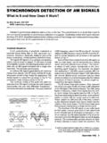
3 In addition, soft processors plus FPGA co-processors enable reconfiguration of the digital waveforms. 2. DIGITAL radio ARCHITECTURE Figure 1 shows a figure of a common FM radio architecture. In traditional radio architectures, all of the FM modulation and demodulation is performed in the analog domain. The processing power of digital components can now easily perform these operations. The first step in digital radio Figure 1: FM radio Architecture architecture is to perform the exact analog functions in the digital domain. This can be done in two ways: 1) perform digital operation on a microprocessor, or 2) create analog equivalent function in digital domain. The most flexible solution is to use a microprocessor (or DSP) to perform the radio functions. This allows the waveform developer to use a standard language, and remain hardware independent.
4 Unfortunately, only low data rate waveforms can be processed using a DSP. The second solution allows for higher processing rates, but is not as flexible. Fortunately, an FPGA s flexibility allows for either solution (or combination of these solutions). 3. PROCESSOR BASED DEMODULATION Figure 2 shows a typical radio system using a microprocessor (or DSP) as the baseband processor. In this case the processing is performed by a soft core microprocessor. Soft core processors are built using the generally available resources in an FPGA. Typically these processors can provide 100 150 MIPS. This is enough processing power to perform modulation and demodulation for low bandwidth signals. When the processing power needed exceeds that of the soft core processor, co-processing elements can be added.
5 Figure 3 shows an example of the same FM radio that uses a CORDIC (COordinate Rotation DIgital Computer) co-processor. The CORDIC co-processor implements a vector rotation engine that can be used to calculate trigonometric Low NoiseAm p lifierFilterVCOVCOP owerAm p lifierFilterVCOVCOS witchAntennaFPGA-based Soft CoreProcessorSoft CoreProcessor(Modulation,Demodulation,Us er InterfaceDigital-to-AnalogAnalog-to-Digi talIn t erfac eMemo ry Figure 2: Processor Based FM radio Low NoiseAm p lifierFilterVCONCOP owerAm p lifierFilterVCONCOS witchFPGA-based Digital IF and Baseband ProcessingSoft CoreProcessor(Modulation,Demodulation,Us er InterfaceMemoryCORDIC Co-processorDigital-to-AnalogAnalog-to-D igitalInt erfac eBuffer Figure 3: FM radio with Digital IF functions [1]. In the case of FM, the CORDIC provides the arctangent function needed to demodulate FM waveforms.))
6 Table 1 shows typical performance of soft core processors and CORDIC co-processors. Table 1: FM radio Components Function Speed Resources Soft core (Altera NIOS) 100 MHz 1500 LE CORDIC 219 MHz 966 LE 4. DIGITAL IF PROCESSING fpgas are capable of more than baseband modulation and demodulation. Today s advanced fpgas have the capability to provide IF (Intermediate Frequency) processing as well as baseband processing. Figure 2 shows the FM radio architecture with IF processing. In this implementation the VCO (Voltage Controlled Oscillator) is replaced with an NCO (Numerically Controlled Oscillator). The analog filtering functions are now replaced by digital FIR (Finite Impulse Response) filters.
7 The Soft core processor (along with the CORDIC co-processor) still performs the baseband processing functions. The Soft core processor also changes the parameters of the various IF components. For example, the Soft core processor can update the output frequency of the NCO, or change the coefficients of the FIR Filter. Today s fpgas are capable of supporting IF rates up to 150 MHz. Table 2 shows some utilization and clock rates for the IF processing functions. The utilizations are based on Altera s Stratix FPGA Family. The resources are as follows: LE: Logic Element, basic element of an FPGA Mult: The number of 18x18 Multipliers used M4K: Embedded 4 Kbit memories Table 2: Digital IF Components Function Speed Resources (LE/Mult/M4K) Parallel FIR (48 taps, 14-bit) MSPS* 1375 / 0 / 30 Serial FIR (48 taps, 14-bit) MSPS* 360 / 0 / 6 NCO (24-bit) MHz 67 / 8 / 12 CIC (6th order, 14-bit) 200 MHz 1138 / 0 / 0 * MSPS: Million Samples Per Second Note: Resources based on [2], [3] 5.
8 IMPLEMENTING SRW The concept of co-processing can be extended to support more computationally intensive waveforms, like SRW. The SRW waveform requires processing rates that are far beyond the reach of microprocessors.. Figure 4 shows the block diagram of the SRW implementation in an FPGA. In this implementation, most of the waveform processing is performed by co-processing components. But, as in the FM case, the Soft core processor performs the initialization and Figure 4: SRW Implementation parameterization of the co-processors. Notice that the CORDIC coprocessor is still available to perform FM waveform processing. Table 3 shows the performance of the various co-processors used in the SRW waveform. Table 3: SRW Components Function Speed Resources (LE/Mult/M4K) FFT* (128 points) sec 4838 / 9 / 19 FFT* (2048 point) sec 7952 / 18 / 44 FFT* (8192 point) sec 8388 / 18 / 176 Viterbi Decoder** 10 Mbps 2600 / 0 / 0 * Two Radix 4 Engines, 16-bit operation ** Constraint length = 7, number ACS = 8 Note: Resources based on [4], [5] 6.
9 SYSTEM IMPLEMENTATION The software-defined radio (SDR) form factor drives the design and power requirements for the design. The SDR system comprises of two modules, the digital baseband module and the RF module. The antenna and Human Machine Interface (HMI) are part of the chassis frame that encloses the RF and Digital module. Through the advancements in package technologies the RF and Digital components on the module can fit into two separate IC packages. Using mixed signal technologies the RF and Digital can fit into one substrate with challenging requirements to minimize interference between the two systems. Limitations in semiconductor technologies can prevent some of the passive components such as capacitors and inductors to meet the stringent RF requirements.
10 A small form factor prototype baseband module measuring 5 square inches, 14 layers, .062 inch thick, three power planes and three supply ground planes, two signal ground planes (analog and digital), and six signal layers provides the necessary isolation to minimize coupling to the RF module. Minimizing the pin count connectivity for the HMI interface and the RF module can do further reduction to the board size. High speed signals around the FPGA are integrated into the inner layers to reduce EMI coupling throughout the digital board. Matched length signal traces for high speed signals ensure the impedance of the signal traces is 50 ohms. The six signal layers are interleaved between the supply planes. All static and control signals with low clock edge rates are routed on the top and bottom layer of the digital board.