Transcription of STK200 AT89S/AT90S Series FLASH …
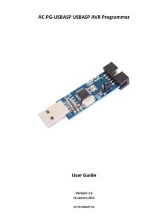
1 STK200 AT89S/AT90S Series FLASH MicrocontrollerStarter KitATMEL Corporation2325 Orchard ParkwaySan Jose, CA 95131 1 Section 1 IntroductionWelcome to the STK200 FLASH MCU starter system incorporates a sophisticated applications board, atmel avr ISP softwareand an ISP dongle that will program any atmel avr microcontroller. For up to the minute information on this product and any manual errata, please read file included with the SupportThe system software currently has support for the following Atmel Devices: AT90S1200 AT90S2313 at90s /LS2323 at90s /LS2343 AT90S4414 at90s /LS4434 AT90S8515 at90s /LS8535 Software upgrades for the AVR ISP software is posted to the AVR section of the Atmelwebsite, which is located at Started2 Getting the SystemContents of box:nEvaluation BoardnDisk set, including atmel avr ISP softwarenIn-System Programming (ISP) DonglenISP Ribbon RequirementsThe minimum hardware and software requirements are.
2 N80386 Processor (486 Recommended)n1MB Ramn1MB Free Hard Disk SpacenWindows or Windows 95 Connecting the Hardware3 Section 2 Connecting the HardwareA power supply is required with a standard barrel connector. It can be AC (7 -12V) or DC (9 - 15V). The connector is inserted into the power connection socket asshown, programming lead supplied is fitted into the Dongle case and the other end isinserted into the programming interface on the board as Dongle case is connected to one of the printer ports on the PC. If this is not LPT1,then you will need to change the printer port setting in the software see software sec-tion for HEADER ON LEAD INTO PROGRAMMING INTERFACE - KEY WAY GIVES ORIENTATIONCONNECT LEADSUPPLIED TO DONGLEAND INSERT INPC PRINTER PORTPOWER SUPPLY9 - 15V DC7 - 12V ACON-OFF SWITCHH ardware Description4 Section 3 Hardware DescriptionThe main features of the board are shown in the following :There are a number of jumpers on the board which are used to select different operations and voltages.
3 The default jumper settings are for programming oper-ations at 5V. To carry out other operations, some jumpers may have to be removed - refer to the relevant section for details. A full list of the jumpers and links are given in Section CONTRASTADJUSTMENTLCD CONNECTORANALOG REFERENCEVOLTAGE ADJUSTMENT28-PIN A/D PARTS (FUTURE)40-PIN A/D PARTSLK1 - CUT FOR A/D EXTERNAL REFERENCEANALOG I/PPORT A DIGITALSOCKET FOR 40-PIN DIGITAL PARTSPORT B - ALL PARTSPORT C - ALL PARTSEXCEPT 28-PINJP3 - JUMPER FORRXD ENABLEPORT D JUMPERSDISABLE SWITCHESPORT D - ALL PARTSEXCEPT 8 PINMISC. HEADERFOR NON-PORT PINSJP2 - JUMPER FOR BROWN-OUT AT OR 5V8 LEDS ONPORT B8 SWITCHESON PORT DJP1 JUMPER OR 5V VCC SELECTON-OFFSWITCHPOWER INPUT9-15V DCOR 7-12 ACRS232 PORT B JUMPERSDISABLE LEDS4 MHZ CRYSTAL20-PIN SOCKETISP INTERFACECLOCK SELECTFOR 8-PIN SOCKET8-PIN SOCKETPOWER ON LIGHTEXTERNAL SRAM SOCKETADDRESSLATCH SOCKET and Links and Their ConnectionsAll Ports are brought out to edge of board on to headers.
4 Each header has a VCC andGround pin for power supply to external circuits. Port A for A/D parts is on a separateheader from Port A for standard parts, labeled Analog. There is an extra six-pin headerfor miscellaneous functions - ICP, OC1B and ALE on 40-pin Digital devices, Reset,Ground and VCC. The external load cannot exceed 100 mA for all headers sections on Using External Connections and Using Analog Parts for out RXDOFFONOpenPort BLEDsLEDs DisabledLEDs EnabledClosedPort DSwitchesSwitches DisabledSwitches EnabledClosedLK1 Analog Reference See Section LK1 cut then EXTERNAL REF from headerONBOARD POTC losedCUT Under BoardLCD ContrastSee Section Cut, add extra resistorContrast PotClosedClock SelSelects Internal or External Clock for AT90S2323 INT = Internal ClockEXT = External ClockClosedInstalling the Software6 Section 4 Installing the 95To install the software.
5 Insert the supplied disk or CDROM in your computer and performthe following steps:1. Click on your Start Select Select Control Choose Add/Remove Click the Install Follow On-Screen software will then be installed onto your computer and an Icon will be added to yourstart menu. RUN from Program Manager, and enter A:\ as the the OK button and the software installation program will software will then be installed onto your computer and an Icon and Program Groupwill be added to Program :On some PCs, especially laptops, programming problems may occur if the Bios Parallel Port settings are set to EPP Version If programming problems do happen, ensure that the Parallel Port settings in your BIOS are set to EPP not the unlikely event that you have any problems installing the software or suspect thatyou have faulty media, please contact the Atmel starter Kit hotline:Hotline Number.
6 (44) 1970 621 049 Fax Number: (44) 1970 621 to use the Software7 Section 5 How to use the SoftwareThe software is fully context-sensitive. This means that pressing F1 at any time will bringup help information about the current option that you have note that the toolbar icons referred to in the text have ToolTip s. If you want toknow the function of any particular button, hold your mouse pointer over the button inquestion and its function will be a ProjectnIn-System-Programming (ISP)nHardware RequirementsnProjectsnData FilesnEditing you have used a high-end professional development system you will be familiar withthe project concept.
7 Essentially this is a collection of information which is managed bythe program on your behalf. In the AVR you have both Program Memory and non-vola-tile Data Memory (EEPROM) and you have various security and device options. Theproject manager keeps this information together for you so you do not have to remem-ber and reload all the various files every time you use the programmer. It will also allow you to store information such as the project name and the project identi-fier. Also included is a small notepad to store comments about the project. Before you can start a programming session you must either open an existing project orstart a new project.
8 You can open a project, or create a new one, by either going to theProject menu and selecting New or Open, or by using the 'New Project' or 'Open Project'buttons on the a project is open, you can load the files that you want to program into the may be loaded by either using the Load command in the File menu or by using theOpen icon on the program will automatically decode your files whether they are in Intel Hex format,Atmel Generic, Binary, or Motorola S record. The file you choose will be loaded into thewindow, then it is displayed on the top of the desktop. If you have the EEPROM DataMemory window on top, then it will load the data into that that the AVR Assembler which accompanies this program will produce the cor-rect files for you ready to load into the buffers.
9 You can save the buffer in Binary, IntelHex, or Atmel Generic formats, so you can use the buffer for code it will load the data into the Program Memory if that is the window that is on program will not allow you to load data if the project manager window is on top. Tochange which window is on top you can either click your mouse on any part of the win-dow that is showing, go to the Window menu using Alt-W or the mouse and select the 8window of your choice or press Ctrl-F6. Note that the loaded data will show up in bluetext where the default, empty text color is your data files are loaded you can start your programming DataOnce a project has been started, you can either load a data file or you can insert yourown data in Hex or ASCII directly into the Program or EEPROM data a new project, the data windows called buffers will contain FF in every is also what a new or erased device will can move around in the current window by using the cursor keys.
10 In order to seememory further down the window, use the page up and page down keys on the may change the data at any memory location by clicking on that location and typingin the required hex values. Any changes you make will be reflected by the data changingto green text. The ASCII character of the hex value will be shown alongside the you wish to edit the buffer in ASCII, either click on the right area of the window orpress you have entered the required data then you can save the contents of the currentwindow by using either the Save icon on the toolbar or by pressing F2 (on the keyboard)or by choosing the Save function in the File menu.
