Transcription of Grid-Connected Solar Microinverter Reference …
1 2012 Microchip Technology 1AN1444 INTRODUCTIONR enewable resources, such as wind generationsystems and Photovoltaic (PV) systems, have gainedgreat visibility during the past few years as convenientand promising, renewable energy sources. There areseveral benefits for Solar power systems, such as: Clean and renewable energy that replaces power produced by coal, oil and nuclear power Reduction/elimination of electric bills Silicon for manufacturing PV panels is the second most abundant element on Earth The ability to provide power to remote locationsThe recent increase in demand for Solar powersystems is due to enhancements in manufacturingcrystalline panels, which reduces overall costs inmanufacturing and increases the efficiency of the PVpanels.
2 Additional reasons for the demand in solarpower are: PV technology is proven and reliable, PVmodules have warranties exceeding 30 years andgovernment are two main requirements for Solar invertersystems: harvest available energy from the PV paneland inject a sinusoidal current into the grid in phasewith the grid voltage. In order to harvest the energy outof the PV panel, a Maximum Power Point Tracking(MPPT) algorithm is required. This algorithm deter-mines the maximum amount of power available fromthe PV module at any given time.
3 Interfacing to the gridrequires Solar inverter systems to abide by certain stan-dards given by utility companies. These standards,such as EN61000-3-2, IEEE1547 and the NationalElectrical Code (NEC) 690, deal with power quality,safety, grounding and detection of islanding of Solar CellsTo begin development of a Solar Microinverter system,it is important to understand the different characteristicsof a Solar cell. PV cells are semiconductor devices withelectrical characteristics similar to that of a diode. How-ever, a PV cell is a source of electricity and operates asa current source when light energy, such as sunlight,makes contact with it.
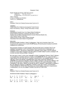
4 The most common technologiestoday are the monocrystalline and multi-crystalline sili-con modules. A PV cell can be modeled as shown inFigure 1. Rp and Rs are parasitic resistances that, in anideal world, would be infinite and zero, 1:SIMPLIFIED MODEL OF A PV CELLA PV cell will behave differently, depending on its sizeor type of load connected to it, and the intensity ofsunlight (illumination). The characteristics of a PV cellare described by the different operating currents andvoltages under different environments. When the cell is exposed to sunlight, but is not con-nected to a load, there is no current flowing through thecell and the voltage across the PV cell reaches its max-imum.
5 This is known as the Open Circuit Voltage (VOC).When the cell is loaded, current begins to flow throughthe circuit and the voltage across the cell begins todrop. The maximum current to pass through the cellcan be determined when the two terminals are directlyconnected to each other and the voltage is zero. This isknown as Short-Circuit Current (ISC).Author:Alex Dumais and Sabarish KalyanaramanMicrochip Technology Solar Microinverter Reference DesignAN1444DS01444A-page 2 2012 Microchip Technology intensity and temperature largely impact theoperating characteristics of a PV cell.
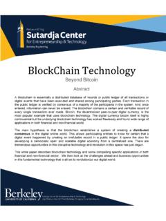
6 Current is directlyproportional to light intensity, but the change in illumina-tion has little impact on the operating voltage. Theoperating voltage is, however, impacted by increase in cell temperature will decrease the operat-ing voltage, but will have little effect on the generatedcurrent. The influence of temperature and illumination ona PV module is illustrated in Figure 2:PV MODULE ELECTRICAL CHARACTERISTICSC hanges in light intensity will have greater effect on thecell output power than changes in temperature. This istrue for all commonly used PV materials.
7 The importantresult of these two effects is that the power of a PV celldecreases when light intensity decreases and/ortemperature Power Point (MPP)A Solar cell may operate over a wide range of voltagesand currents. By continuously increasing the resistiveload on an irradiated cell from zero (short-circuit event)to a very high value (open circuit event), the MPP canbe determined. MPP is the operating point that maxi-mizes, V x I, and delivers the maximum power at thatirradiation. The output power in a short-circuit (PVvoltage equals zero) or open circuit (PV current equalszero) event is high quality, monocrystalline silicon Solar cell, at25 C cell temperature, may produce volts opencircuit.
8 The temperature on a given cell in full sunlight,with an air temperature of 25 C, may be closer to 45 Cwhich will reduce the open circuit voltage to ~ Astemperature rises, the open circuit voltage continues todrop until there is a short circuit on the PV maximum power at a cell temperature of 45 C istypically produced with 80% of the open circuit voltageand 90% of the short-circuit current. The short-circuitcurrent from a cell is nearly proportional to the illumina-tion, while the open circuit voltage may drop 10% withan 80% drop in illumination. Lower quality cells have amore rapid drop in voltage with increasing current,which would reduce the usable power output from 70%to 50% or even as little as 25%.
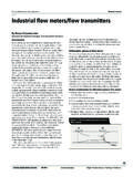
9 Figure 3 shows the output current and output power ofa PV panel as a function of operating voltage for agiven illumination. FIGURE 3:MPPT CHARACTERISTICS OF A PV MODULEThe Solar Microinverter must ensure that the PV moduleis operating at the MPP to capture the maximum energyfrom the PV module, at any given time. This is accom-plished by the Maximum Power Point control loop,known as the Maximum Power Point Tracker (MPPT).Achieving a high percentage of MPP tracking alsorequires the PV output voltage ripple to be sufficientlysmall, in order to operate around the Maximum PowerPoint without too much variation in PV current.
10 See the Decoupling Capacitors section for more details onlimitation of the PV module output voltage ripple. Referto the Maximum Power Point (MPP) section for moredetails on implementing MPPT. A common MPP voltage range for PV modules can bedefined in the range of 25V to 45V, at a power genera-tion of approximate 250W, with an open circuit voltagebelow 50V. VoltageCurrentI-V vs. Illumination1020304050642642 VoltageCurrentI-V vs. Temperature102030405010 C60 CMaximum Power PointMaximum Power PointVoltagePowerMaximum Power Point1020304050225 W150 W75 2012 Microchip Technology 3AN1444 Introduction of a Grid-Connected Microinverter SystemA high-level block diagram of a Grid-Connected solarmicroinverter system is shown in Figure 4.