Transcription of High Precision Bulk Metal Sensing Chip Resistor with TCR ...
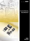
1 High Precision Bulk Metal Foil Surface Mount CurrentSensing chip Resistor with TCR of 2 ppm/ C andLoad Life Stability of %VCS1625 Vishay Foil Resistors Document Number: 63023 For any questions, contact: 23-Mar-101 INTRODUCTIONM odel VCS1625 is a surface mount Resistor designed with4 pads for Kelvin connection. Utilizing Vishay Bulk Metal foil as the resistance element, it provides performancecapabilities far greater than other Resistor technologies cansupply in a product of comparable small device dissipates heat almost entirely through thepads so surface mount users are encouraged to be generouswith the board s pads and traces. Gold terminations areavailable on special application engineering department is available toadvise and to make recommendations. For non standardtechnical requirements and special applications, pleasecontact (1)Power rating at + 70 C: W on FR4 PCBFEATURES Temperature coefficient of resistance (TCR): ppm/ C typical (- 55 C to + 125 C,+ 25 C ref.)
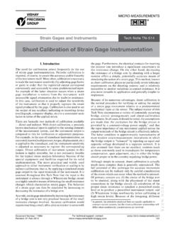
2 (see table 1) Resistance range: to 10 (for higher orlower values please contact us) Vishay Foil resistors are not restricted tostandard values, we can supply specific as required values at no extra cost or delivery ( vs. 1 ) Tolerance: to % Load life stability: % at 70 C, 2000 h at rated power Electrostatic discharge (ESD) up to 25 000 V Short time overload % Non inductive, non capacitive design Power rating: W at + 70 C (figure 1) or 5 A, whicheveris lower Thermal EMF: V/ C typical Non hot spot design current noise: < - 40 dB Rise time: 1 ns effectively no ringing Voltage coefficient: < ppm/V Non inductive: < H For better performances please review VCS1625Z (Z-foil)datasheetTERMINATIONS Two lead (Pb)-free options are available:gold plated or tin plated Tin/lead platedAPPLICATIONS Automatic test equipment (ATE) Airborne (in heads-up display systems) High Precision instrumentation Electron beam recording equipment Electron microscopes current Sensing applications Forced balance electronic scales Applications that require superior frequency stability Military Medical* Pb containing materials are not RoHS compliant, exemptions may applyFIGURE 1 - POWER DERATING CURVE (1)1007550250- 75- 50- 250+ 25 + 50 + 75 + 100 + 125 + 150 + 175 Ambient Temperature ( C) Percent of Rated Power + 70 C- 55 CI1E1I2E2 ElectricalSchematicRTABLE 1 - TOLERANCE AND TCR VS.
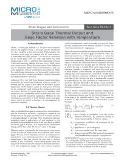
3 RESISTANCE VALUE (- 55 C to + 125 C, + 25 Ref.)VAL UE ( )TOLERANCETYPICAL TCRMAXIMUM TCR> 2R000 to %, %, 1 % 2 ppm/ C 5 ppm/ C> 0R500 to %, 1 % 2 ppm/ C 10 ppm/ C> 0R100 to 0R5001 % 2 ppm/ C 15 ppm/ C> 0R050 to 0R1001 % 2 ppm/ C 20 ppm/ C> 0R030 to 0R0501 % 2 ppm/ C 30 ppm/ C> 0R010 to 0R0301 % 2 ppm/ C 50 ppm/ CVCS1625 Vishay Foil Resistors any questions, contact: Number: 630232 Revision: 23-Mar-10 Note Measurement error 2 - DIMENSIONS in Inches (Millimeters) Pad LayoutTop ViewBottom ViewMountingPads (4) ( )( ) ( ) ( )FIGURE 1 - TRIMMING TO VALUES(Conceptual Illustration)Mutual InductanceReduction dueto OpposingCurrent inAdjacent LinesCurrent PathBefore TrimmingNote: Foil shown in black, etched spaces in whiteInterloop CapacitanceReduction in SeriesTrimming ProcessRemoves this Materialfrom Shorting Strip AreaChanging current Pathand IncreasingResistanceCurrent PathAfter TrimmingFIGURE 4 - TYPICAL TCR CURVE+ 75+ 150+ 100+ 50 0- 50- 100- 150- 200 Ambient Temperature ( C) RR(ppm) 2 ppm/ C (+ 25 C reference)+ 100+ 125- 250+ 25+ 50- 50 TABLE 2 - PERFORMANCE SPECIFICATIONSTESTMIL-PRF-55342 R LIMITSTYPICAL R LIMITSMAXIMUM R LIMITST hermal Shock 5 x (- 65 C to + 150 C) % % (50 ppm) % (100 ppm)Low Temperature Operation % % (50 ppm) % (100 ppm)Short Time Overload % % (50 ppm) % (200 ppm)High Temperature Exposure % % (100 ppm) % (200 ppm)Resistance to Soldering Heat % % (100 ppm) % (300 ppm)Moisture Resistance % % (100 ppm) % (300 ppm)Load Life 2000 h at 70 C.
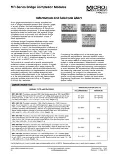
4 Rated Power On Ceramic PCB % % (200 ppm) % (400 ppm)VCS1625 Vishay Foil Resistors Document Number: 63023 For any questions, contact: 23-Mar-103 Note(1)For non-standard requests or additional values, please contact application 3 - GLOBAL PART NUMBER INFORMATIONNEW GLOBAL PART NUMBER: Y08501R50500D9L (preferred part number format)DENOTES PRECISIONVALUEAER (1)YR = 0 = standard part, tin/lead termination9 = standard part, lead (Pb)-free termination129 = gold plated1 to 999 = customPRODUCT CODERESISTANCE TOLERANCEPACKAGING0850 = VCS1625B= %E= %D= %F= %G= %J= %K= %W= waffle packR= tape and reelFOR EXAMPLE: ABOVE GLOBAL ORDER Y0850 1R50500 D 9 W:TYPE: VCS1625 VALUES: ABSOLUTE TOLERANCE: %TERMINATION: tin plated (lead (Pb)-free)PACKAGING: bulk packHISTORICAL PART NUMBER: VCS1625 1R5050 TCR2 D S W (will continue to be used)VCS16251R50500 TCR2 DSWMODELOHMIC VALUETEMPERATURE COEFFICIENT CHARACTERISTICRESISTANCE B= %E= %D= %F= %G= %J= %K= %S= lead (Pb)-freeB= tin/leadG= gold platedW= waffle packT= tape and reel8501505RY0090 WDVishay Precision Group, Disclaimer NoticeDocument No.
5 : 63999 Revision: 15-Jul-2014 DisclaimerALL PRODUCTS, PRODUCT SPECIFICATIONS AND DATA ARE SUBJECT TO CHANGE WITHOUT Precision Group, Inc., its affiliates, agents, and employees, and all persons acting on its or their behalf (collectively, VPG ), disclaim any and all liability for any errors, inaccuracies or incompleteness contained herein or in any other disclosure relating to any product specifications do not expand or otherwise modify VPG s terms and conditions of purchase, including but not limited to, the warranty expressed makes no warranty, representation or guarantee other than as set forth in the terms and conditions of purchase. To the maximum extent permitted by applicable law, VPG disclaims (i) any and all liability arising out of the application or use of any product, (ii) any and all liability, including without limitation special, consequential or incidental damages, and (iii) any and all implied warranties, including warranties of fitness for particular purpose, non-infringement and provided in datasheets and/or specifications may vary from actual results in different applications and performance may vary over time.
6 Statements regarding the suitability of products for certain types of applications are based on VPG s knowledge of typical requirements that are often placed on VPG products. It is the customer s responsibility to validate that a particular product with the properties described in the product specification is suitable for use in a particular application. You should ensure you have the current version of the relevant information by contacting VPG prior to performing installation or use of the product, such as on our website at license, express, implied, or otherwise, to any intellectual property rights is granted by this document, or by any conduct of products shown herein are not designed for use in life-saving or life-sustaining applications unless otherwise expressly indicated. Customers using or selling VPG products not expressly indicated for use in such applications do so entirely at their own risk and agree to fully indemnify VPG for any damages arising or resulting from such use or sale.
7 Please contact authorized VPG personnel to obtain written terms and conditions regarding products designed for such names and markings noted herein may be trademarks of their respective Vishay Precision Group, Inc., 2014. All rights Disclaimer Notic