Transcription of INA3221 Triple-Channel, High-Side Measurement, Shunt and ...
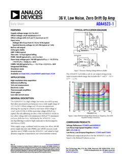
1 Power Supply (0 V to 26 V)Load 1 Load 2 Power Supply (0 V to 26 V)Load 3 Power Supply (0 V to 26 V) FVS (Supply Voltage)CH 1CH 2 VIN 1 VIN+1 VIN 2 VIN+2CH 3 VIN 3 VIN+3I2C-andSMBus-CompatibleInterfaceSDA SCLA0 CriticalWarningGNDADCS huntVoltages 1-3 Critical Limit Alerts 1-3 BusVoltages 1-3 Power Valid (PV)Timing Control (TC) Shunt Voltage Sum Alerts VSVPU10 k VPU10 k ProductFolderSample &BuyTechnicalDocumentsTools &SoftwareSupport &CommunityAn IMPORTANTNOTICEat the end of this datasheetaddressesavailability,warranty, changes,use in safety-criticalapplications,intellectual propertymattersand MAY2012 REVISEDMARCH2016 INA3221 Triple-Channel, High-SideMeasurement,Shun tand Bus VoltageMonitorwith I2C- and SMBUS-CompatibleInterface11 Features1 SensesBus VoltagesFrom0 V to 26 V ReportsShuntand Bus Voltage HighAccuracy: OffsetVoltage.
2 80 V (max) (max) ConfigurableAveragingOptions FourProgrammableAddresses ProgrammableAlertand WarningOutputs Power- V to V2 Applications Computers PowerManagement TelecomEquipment BatteryChargers PowerSupplies TestEquipment3 DescriptionTheINA3221is a three-channel,high-sidecurrentand bus voltagemonitorwithan I2C- and ,inadditionto havingprogrammableconversiontimesand averagingmodesfor INA3221offersbothcriticalandwarningalert sto INA3221sensescurrenton busesthat can varyfrom0 V to 26 V. Thedeviceis ,and draws350 A (typ)of INA3221is specifiedovertheoperatingtemperaturerang eof 40 C to +125 and SMBUS-compatibleinterfacefeaturesfour (1)PARTNUMBERPACKAGEBODYSIZE(NOM) INA3221 VQFN(16) x (1) For all availablepackages,see the packageoptionaddendumat the end of the MAY2012 : INA3221 SubmitDocumentationFeedbackCopyright 2012 2016,TexasInstrumentsIncorporatedTableof Contents1 Pin Configurationand Applicationand Deviceand Mechanical,Packaging,and RevisionHistoryNOTE.
3 Pagenumbersfor previousrevisionsmay differfrompagenumbersin the (June2013)to RevisionBPage AddedDeviceInformationandESDR atingstables,andFeatureDescription,Devic eFunctionalModes,Applicationand Implementation,PowerSupplyRecommendation s,Layout,Deviceand DocumentationSupport, andMechanical,Packaging,and DeletedtracefromSDAto SCL,and addedmissingconnectordot to VSin Added(VIN+) + (VIN ) / 2 to common-modeanaloginputsin Changedall VSENSEto VSHUNT throughoutdatasheetfor Changed"Statusregister" to "Mask/Enableregister" to ChangedCriticalAlertsectiontext for Changedexternal"RPU" to "RPU_ext" in Figure20 ..14 ChangedMultipleChannelMonitoringsectiont ext for AddedX and Y axis labelsto Changed"bidirectional" to "I/O" in secondparagraphofBus ChangedVS+to VS in Changedreferencesin Figure30 to pointto Changedvaluesin Table2,Bus Addeddatavalidtime to Table2,Bus Changedfall time to split dataand clocktimesin Table2,Bus Deletedrise time for datain Table2,Bus DeletedtracefromSDAto SCL,and addedmissingconnectordot to VSin Figure52.
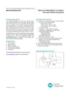
4 MAY2012 REVISEDMARCH2016 ProductFolderLinks: INA3221 SubmitDocumentationFeedbackCopyright 2012 2016,TexasInstrumentsIncorporatedChanges fromOriginal(May2012)to RevisionAPage ChangedsecondparagraphofSerialBus UpdatedFigure27 and note(1) ..21 UpdatedFigure28 and note(1) ..21 UpdatedFigure29 and note(1) ..22 UpdatedFigure30 and note(1) ..22 Changedbit D15 in Changedbit D15 in 3IN+3 GNDVSIN+1IN 1 PVCritical12341211109 VPUIN+2IN 2TC16151413A0 SCLSDAW arning56784 INA3221 SBOS576B MAY2012 : INA3221 SubmitDocumentationFeedbackCopyright 2012 2016,TexasInstrumentsIncorporated5 DeviceComparisonTableDEVICEDESCRIPTIONIN A22636-V,Bidirectional,UltrahighAccuracy ,Low-or High-Side ,I2C Out, Currentand PowerMonitorWithAlertINA21926-V,Bidirect ional, zero - drift , High-Side ,I2C Out, Currentand PowerMonitorINA20926-V,Bidirectional,Low -or High-Side ,I2C Out, Currentand PowerMonitorand High-SpeedComparatorINA210, INA211, INA212,INA213, INA21426-V,Bidirectional, zero - drift ,High -Accuracy,Low-or High-Side ,VoltageOut, CurrentShuntMonitor6 Pin Configurationand FunctionsRGVP ackage16-PinVQFNTop ViewPin Connectto GND,SCL,SDA,or VS.
5 Table1 showspin ; 111 AnaloginputConnectto load side of the channel1 voltageis the measurementfromthis pin to +112 AnaloginputConnectto supplyside of the channel1 214 AnaloginputConnectto load side of the channel2 voltageis the measurementfromthis pin to +215 AnaloginputConnectto supplyside of the channel2 31 AnaloginputConnectto load side of the channel3 voltageis the measurementfromthis pin to +32 AnaloginputConnectto supplyside of the channel3 ; clockline; dataline; open- ; bias , V to ; MAY2012 REVISEDMARCH2016 ProductFolderLinks: INA3221 SubmitDocumentationFeedbackCopyright 2012 2016,TexasInstrumentsIncorporated(1)Stre ssesbeyondthoselistedunderAbsoluteMaximu mRatingsmay causepermanentdamageto the stressratingsonly,whichdo not implyfunctionaloperationof the deviceat theseor any otherconditionsbeyondthoseindicatedunder RecommendedOperatingConditions.
6 Exposureto absolute-maximum-ratedconditionsfor extendedperiodsmay affectdevicereliability.(2)VIN+and VIN can havea differentialvoltageof 26 V to +26 V; however,the voltageat thesepins mustnot exceedthe rangeof V to +26 (unlessotherwisenoted)(1)MINMAXUNITV oltageSupply,VS6 VAnaloginputsIN+, IN Differential(VIN+) (VIN )(2) 2626 VCommon-mode(VIN+) + (VIN ) / 2 ,warning,powervalid6 VTimingcontrol26 SerialbusDataline, SDA(GND )6 VClockline, SCL(GND )(VS+ )CurrentInput,into any pin5mAOpen-drain,digitaloutput10 TemperatureOperating,TA 40125 CJunction,TJ150 Storage,Tstg 65150(1)JEDEC documentJEP155statesthat 500-VHBM allowssafe manufacturingwith a standardESDcontrolprocess.(2)JEDEC documentJEP157statesthat 250-VCDM allowssafe manufacturingwith a (ESD)ElectrostaticdischargeHuman-bodymod el(HBM),per ANSI/ESDA/JEDECJS-001(1) 2500 VCharged-devicemodel(CDM),per JEDEC specificationJESD22-C101(2) 1000 Machinemodel (unlessotherwisenoted) ,TA 40125 C(1)For moreinformationabouttraditionaland new thermalmetrics,see theSemiconductorand IC PackageThermalMetricsapplicationreport(S PRA953).
7 (1) INA3221 UNITRGV(VQFN)16 PINSR C/WR JC(top)Junction-to-case(top) C/WR C/W C/W C/WR JC(bot)Junction-to-case(bottom) C/W6 INA3221 SBOS576B MAY2012 : INA3221 SubmitDocumentationFeedbackCopyright 2012 2016,TexasInstrumentsIncorporated(1)RTI = Referred-to-input.(2)Inputleakageis positive(currentflowsinto the pin) for the conditionsshownat the top of this occurunderdifferentinputconditions.(3)SM Bustimeoutsin the INA3221resetthe interfacewheneverSCLis low for morethan28 TA= 25 C, VS= V, VIN+= 12 V, VSHUNT= (VIN+) (VIN ) = 0 mV, and VBUS= VIN = 12 V (unlessotherwisenoted)PARAMETERTESTCONDI TIONSMINTYPMAXUNITINPUTVSHUNTS huntvoltageinput voltageinput026 VCMRC ommon-moderejectionVIN+= 0 V to +26 V110120dBVOSS huntoffsetvoltage,RTI(1) 40 80 VTA= 40 C to +125 V/ CPSRRvs powersupply,VS= V to V15 V/VVOSBus offsetvoltage,RTI(1) 8 16mVTA= 40 C to +125 C80 V/ CPSRRvs +Inputbias currentat IN+10 AIIN Inputbias currentat IN 10 || 670 A || k Inputleakage(2)(IN+ pin) + (IN pin)
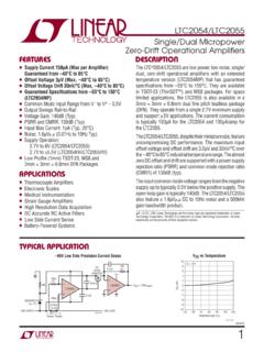
8 , ADC ACCURACYADC nativeresolution13 Bits1-LSBstep sizeShuntvoltage40 VBus voltage8mVShuntvoltagegain 40 C to +125 C1050ppm/ CBus voltagegain 40 C to +125 C1050ppm/ CDNLD ifferentialnonlinearity bit = 000140154 sCT bit = 001204224CT bit = 010332365CT bit = 011588646CT bit = bit = bit = bit = (3)2835msDIGITALINPUT/OUTPUTCII nputcapacitance3pFLeakageinputcurrent0 V VIN (VS)6 VVILLow-levelinputvoltage (VS)VVOLLow-leveloutputvoltageSDA,critic al,warning,PVVS> + , IOL= 3 > + , IOL= Gain Error (%) 50 250255075100125150 Temperature ( C)Input Gain Error (m%)G007 3035404550 50 250255075100125150 Temperature ( C)Input Offset Voltage ( V)G004 115120125130 50 250255075100125150 Temperature ( C)Common Mode Rejection (dB)G005 160 120 80 4004080120200 Input Offset Voltage ( V)PopulationG003160 60 50 40 30 20 1001101001k10k100kFrequency (Hz)Gain (dB)G001 MAY2012 REVISEDMARCH2016 ProductFolderLinks: INA3221 SubmitDocumentationFeedbackCopyright 2012 2016, TA= 25 C, VS= V, VIN+= 12 V, VSHUNT= (VIN+) (VIN ) = 0 mV, and VBUS= VIN = 12 V (unlessotherwisenoted)Figure1.
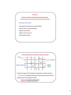
9 FrequencyResponseFigure2. ShuntInputOffsetVoltageProductionDistrib utionFigure3. ShuntInputOffsetVoltagevs TemperatureFigure4. ShuntInputCommon-ModeRejectionRatiovsTem peratureFigure5. ShuntInputGainErrorProductionDistributio nFigure6. ShuntInputGainErrorvs Temperature050100150200250300350400 50 250255075100125150 Temperature ( C)Input Gain Error (m%)G012 051015202530354045500481216202428 Common Mode Input Voltage (V)Input Bias Current ( A)IB+IB G013 Gain Error (%)PopulationG011 16 12 8 4048 50 250255075100125150 Temperature ( C)Input Offset Voltage (mV)G010 24 16 808162432 3234 Input Offset Voltage (mV)PopulationG009501001502000246810 12 14 16 18 20 22 24 26 Common Mode Input Voltage (V)Input Gain Error (m%)G008 8 INA3221 SBOS576B MAY2012.
10 INA3221 SubmitDocumentationFeedbackCopyright 2012 2016,TexasInstrumentsIncorporatedTypical Characteristics(continued)at TA= 25 C, VS= V, VIN+= 12 V, VSHUNT= (VIN+) (VIN ) = 0 mV, and VBUS= VIN = 12 V (unlessotherwisenoted)Figure7. ShuntInputGainErrorvs Common-ModeVoltageFigure8. Bus InputOffsetVoltageProductionDistribution Figure9. Bus InputOffsetVoltagevs TemperatureFigure10. Bus InputGainErrorProductionDistributionFigu re11. Bus InputGainErrorvs TemperatureFigure12. InputBiasCurrentvs (MHz)Quiescent Current ( A)G018 (MHz)Quiescent Current ( A)G019 200250300350400450500 50 250255075100125150 Temperature ( C)Quiescent Current ( A)G016 50 250255075100125150 Temperature ( C)Quiescent Current ( A)G017 051015202530 50 250255075100125150 Temperature ( C)Input Bias Current ( A)IB+IB G014 050100150200250300350400450 50 250255075100125150 Temperature ( C)Input Bias Current (nA)IB+, IB G015 MAY2012 REVISEDMARCH2016 ProductFolderLinks: INA3221 SubmitDocumentationFeedbackCopyright 2012 2016,TexasInstrumentsIncorporatedTypical Characteristics(continued)at TA= 25 C, VS= V, VIN+= 12 V, VSHUNT= (VIN+) (VIN ) = 0 mV, and VBUS= VIN = 12 V (unlessotherwisenoted)Figure13.