Transcription of INSTALLATION INSTRUCTIONS FOR PART 99-9700
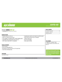
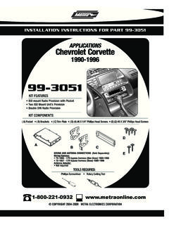
1 APPLICATIONSMETRA. The World s best kits. COPYRIGHT 2015 METRA ELECTRONICS CORPORATION REV. 4/23/2015 INST99-9700 CAUTION: Metra recommends disconnecting the negative battery terminal before beginning any INSTALLATION . All accessories, switches, and especially air bag indicator lights must be plugged in before reconnecting the battery or cycling the : Refer to the INSTRUCTIONS included with the aftermarket INSTRUCTIONS FOR PART 99-9700 ISO DIN radio provision Included interface and LCD info screen A) Radio housing B) Radio brackets C) LCD screen D) LCD back plate E) (10) #8 x 3/8 Phillips screws Axxess interface (not shown)KIT FEATURESKIT COMPONENTSWIRING & ANTENNA CONNECTIONS (sold separately)Wiring Harness: Included interface Antenna Adapter: 40-EU10 Handle bar controls.
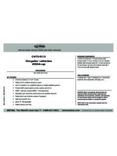
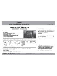
2 ASWC-1 Panel removal tool Phillips screwdriver Torx screwdrivers Allen wrenchesTOOLS REQUIREDH arley-Davidson Street Glide, Electra Glide, Ultra and Limited models 2014-up / Road Glide 2015-up99-9700 ABCDEF airing Disassembly Harley Davidson Street Glide, Electra Glide, Ultra, and Limited models 2014-up ..2-3 Harley Davidson Road Glide 2015-up ..4 Kit Assembly ..5 Axxess interface INSTALLATION ..6-7 Troubleshooting/Updating 99-9700 ..8 Table of Contents99-97002 Harley Davidson Street Glide, Electra Glide, Ultra, and Limited models 2014-up Disassembly1. Remove (4) T-27 from inner fairing. (Figure A)2. Remove (3) T-27 from windshield (caution not to drop the outer fairing or windshield).
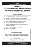
3 (Figure B)3. Remove outer fairing, unplugging the headlight. (Figure C)4. Remove (2) T-27 to remove the fairing vent and remove the vent. (Figure D) Continued on next page(Figure C)(Figure A)(Figure D)(Figure B)99-97003 Harley Davidson Street Glide, Electra Glide, Ultra,and Limited models 2014-up Disassembly5. Remove (11) screws securing the radio bracket: (Figure E) (2) T-27 Torx screws shared with the gauge cluster and a third T-27 Torx screw to remove the gauge cluster in step (4) 5/32 Allen screws facing (4) T-25 Torx screws secured to the (1) T-25 Torx screw shared with the storage Remove the radio bracket. (Figure E) Note: This bracket will be reused with the 99-9700 kit.
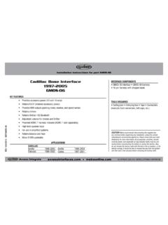
4 7. Remove the gauge cluster. (Figure E)8. Remove (4) 3/16 Allen screws from the sides of radio. (Figure F) Note: These screws will be reused with the 9700 kit. 9. Slide the radio out toward the rear of the bike, and unplug the radio. (Figure F)(Figure E)(Figure F)99-97004 Harley Road Glide 2015-up Disassembly1. Remove the lower torx screws on either side holding the wind deflector wings (only the lower two need to be removed). (Figure A)2. Remove (1) 3/16 Allen screw securing each turn signal. (Figure B)3. Remove (4) Phillips screws from the windshield and set the windshield aside. (Figure C)4. Remove the top fairing trim clipped to the top of the radio.
5 (Figure D)5. Unplug the turn Remove the speaker grills with a panel removal tool and remove (1) torx screw from each side. (Figure E) CAUTION: The fairing will be loose at this point. Have a helper hold it to keep from damaging it when removing the Remove the fairing and set Remove (4) 3/16 Allen screws from the sides of the : These screws will be reused with the 9700 : Be sure to hold the radio when removing the last screw so it will not Unplug and remove the Remove (2) Torx screws securing the fairing bracket attached to the : This bracket will be reused with the 99-9700 kit. Please note the orientation of the bracket.
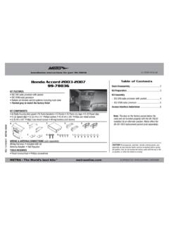
6 The curved portion faces the rear of the bike.(Figure C)(Figure B)(Figure E)(Figure A)(Figure D)99-97005 Kit Assembly1. Secure the radio brackets to the radio housing with (4) #8 x 3/8 Phillips screws supplied. (Figure A)2. Remove the metal DIN sleeve and trim ring from the aftermarket Slide the radio into the radio housing assembly and secure with screws supplied with the radio. (Figure B)4. Insert the LCD screen into the radio housing, route the cable through the LCD back plate, and then secure to the radio housing assembly using (2) #8 x 3/8 screws supplied with the kit. (Figure C)5. Secure the radio housing assembly to the bike using (4) 3/16 Allen screws previously removed in step 8 of disassembly.
7 (Figure D)6. (a) For the Street Glide, Electra Glide, Ultra, and Limited models 2014-up; Attach the radio bracket removed in step 6 of disassembly to the top of the radio housing assembly, and secure with (4) Phillips screws supplied. (b) For the Road Glide 2015-up; Attach the fairing bracket removed in step 10 of disassembly to the top of the radio housing assembly, and secure with (2) Phillips screws supplied. Ensure the bracket is far forward, and the curved portion is facing the rear of the bike as mentioned in Locate the factory wiring harness and antenna plug in the dash. Refer to the interface wiring INSTRUCTIONS on pages Reassemble the fairing in reverse order of disassembly, and then pull the screen protector off from the LCD screen.
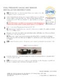
8 (Figure A)(Figure B)(Figure C)(Figure D)99-97006 Provides accessory power (12-volt 10-amp) High level speaker input Retains balance and fade Retains oil pressure and EITMS status Prewired ASWC-1 harness included (ASWC-1 sold separately) Micro B USB updatableFEATURES Cutting tool Crimping tool Tape Connectors (example: butt-connectors, bell caps, etc.)TOOLS REQUIRED 99-9700 interface 99-9700 harnessINTERFACE COMPONENTSFrom the 99-9700 harness to the aftermarket radio: Connect the Black wire to the ground wire. Connect the Yellow wire to the battery wire. Connect the Red wire to the accessory wire.
9 Connect the Orange wire to the illumination wire. (If the aftermarket radio has no illumination wire, tape off the Orange wire). Connect the White wire to the left front positive speaker output. Connect the White/Black wire to the left front negative speaker output. Connect the Gray wire to the right front positive speaker output. Connect the Gray/Black wire to the right front negative speaker output. Connect the Green wire to the left rear positive speaker output. Connect the Green/Black wire to the left rear negative speaker output. Connect the Purple wire to the right rear positive speaker output. Connect the Purple/Black wire to the right rear negative outputFrom the 12-pin pre-wired ASWC-1 harness to the aftermarket radio: This harness is to be used along with the optional ASWC-1 (not included) to retain handlebar controls.
10 If the ASWC-1 is not being used, disregard this harness. If it will be used, please refer to the ASWC-1 INSTRUCTIONS for radio connections and : Disregard the harness that comes with the ASWC-1 Connections to be madeAxxess Interface Installation99-97007 LCD Operation* The included LCD screen provides oil pressure and EITMS status. For more information, please see the owner s manual that came with the menu options: Red adjusts the red backlighting of the LCD (ranges from 1 to 32). Blue adjusts the blue backlighting of the LCD (ranges from 1 to 32). Green adjusts the green backlighting of the LCD (ranges from 1 to 32). Contrast adjusts the contrast of the LCD (ranges from 1 to 100).