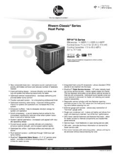
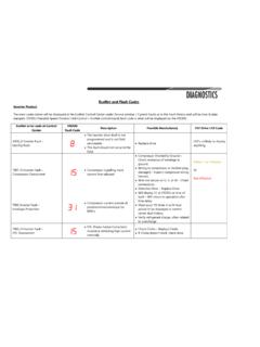
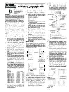
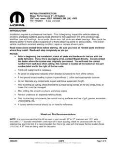
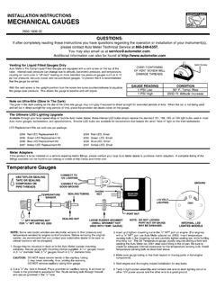
Transcription of INSTALLATION INSTRUCTIONS - MyRheem.com
1 ISO 9001:2008 INSTALLATION INSTRUCTIONSFOR DOWNFLOW SINGLE STAGE GAS FURNACES WITHCONSTANT TORQUE AIR CIRCULATING BLOWER(-)801T DOWNFLOW SERIES(-)(-)80 DSX DOWNFLOW SERIES and/or recognized fuel gas and CO (carbon monoxide) detectors are rec-ommended in all applications, and their INSTALLATION should be in accordance with themanufacturer s recommendations and/or local laws, rules, regulations, or 92-24161-145-052 ContentsTABLE OF CONTENTS 1 TABLE OF CONTENTS.. 2 2 GENERAL INFORMATION .. 3 Receiving .. 4 California Proposition 65 Note .. 4 Checklist .. 5 3 SAFETY INFORMATION .. 6 Warnings .. 6 Important Information About Efficiency and Quality.. 7 4 LOCATION REQUIREMENTS .. 8 Site Selection .. 8 Clearance Accessibility .. 8 Upflow Dimensions & Clearance Table.
2 9 5 DUCTING .. 10 Downflow Installations .. 10 6 COMBUSTION AND VENTILATION AIR .. 12 Combustion Air Requirements .. 12 Venting .. 16 B-1 Vertical Venting .. 16 Special Vent Systems (SVS) .. 17 Power Vent Systems .. 18 Existing Vent Systems .. 18 7 GAS SUPPLY .. 19 Gas Supply and Piping .. 19 Gas Piping .. 20 Gas Pressure .. 21 Setting Gas Pressure .. 22 9 ELECTRICAL WIRING .. 23 Reversing the Electrical Connection .. 23 Thermostat .. 24 8 LP CONVERSION .. 25 10 ACCESSORIES .. 26 Field Installed Option Accessories .. 26 Humidifier .. 26 4-Inch Flue Adapter .. 26 Filters .. 26 RXGW-B01 Chimney Adapter .. 26 11 TWINNING .. 27 Furnace Twinning Installations.
3 27 Control Boards .. 28-29 12 HIGH ALTITUDE .. 30 Natural Gas at High Altitudes .. 30 LP Gas at High Altitudes.. 32 13 STARTUP PROCEDURES .. 33 Sequence of Operation .. 33 14 DIAGNOSTICS & FAULT CODES .. 34 15 LOCKOUT .. 35 16 FIELD SELECTIONS & ADJUSTMENTS .. 36 Field Selections Dipswitches.. 36 17 FAULT CLEAR .. 37 18 FAULT RECALL .. 37 19 FLAME STATUS .. 37 20 TIMING DIAGRAM.. 37 21 ADJUSTING OR CHECKING FURNACE INPUT . 38 22 SETTING INPUT RATE .. 39 23 AIRFLOW .. 40 Blower Speed Selection .. 41 24 SAFETY FEATURES .. 42 25 MAINTENANCE .. 43 Gas Furnace (Direct Drive) INSTRUCTIONS .. 43 Filters .. 43 Lubrication .. 43 26 SYSTEM OPERATION INFORMATION .. 44 27 ANNUAL INSPECTION .. 45 28 REPLACEMENT PARTS.
4 45 24 DIAGNOSTICS.. 46 30 WIRING DIAGRAM .. 47 IMPORTANT:TO INSURE PROPER INSTALLATION AND OPERATION OF THIS PRODUCT, COMPLETELY READ ALL INSTRUC-TIONS PRIOR TO ATTEMPTING TO ASSEMBLE, INSTALL, OPERATE, MAINTAIN OR REPAIR THIS PRODUCT. UPON UNPACKINGOF THE FURNACE, INSPECT ALL PARTS FOR DAMAGE PRIOR TO INSTALLATION AND InformationGENERAL INFORMATIONNOTE: A heat loss calculation should be performed to properlydetermine the required furnace BTU size for the structure. Also,the duct must be properly designed and installed for proper air-flow. Existing ductwork must be inspected for proper size and tomake sure that it is properly sealed. Proper airflow is necessaryfor both user comfort and equipment opening the furnace carton, verify that the data tags onthe carton specify the furnace model number that was orderedfrom the distributor and are correct for the INSTALLATION .
5 If not,return the unit without opening the carton. If the model numberis correct, open the carton and verify that the furnace ratinglabel specifies the same furnace model number that is speci-fied on the carton label. If the model numbers do not match, re-turn the furnace to the : Proper application, INSTALLATION and maintenance ofthis furnace and system is a must if consumers are to receive the fullbenefits for which they have (-)801T/(-)(-)801 DSX series furnaces are design certified byCSA for use with natural and propane gases as follows:As a Category I furnace, it may be vented vertically with type B-1 vent pipe and also may be common vented as described inthese furnace should be installed in accordance with the AmericanNational Standard - latest edition booklet entitled NationalFuel Gas Code (NFPA 54), and the requirements or codes of thelocal utility or other authority having jurisdiction including localplumbing or waste water the introduction of higher efficiency furnaces, special attentionmust be paid to the venting system.
6 Only listed venting systemsmay be used as stated in the INSTALLATION INSTRUCTIONS and the Na-tional Fuel Gas Code, ANSI (NFPA 54),. Since furnacetechnology and venting requirements are changing, awareness oflocal, state, and federal codes and industry changes is BOXDOOR SWITCHMAIN PRESSURE SWITCHINDUCED DRAFT BLOWER (IDB)MAIN LIMITBURNERFLAME SENSOROVER TEMPERATURE SWITCHIGNITOR GAS VALVEGAS VALVETRANSFORMERFLUE PIPE ENCLOSUREHEAT ASSISTED LIMIT CONTROL (HALC)FLUE CONNECTIONCONTROL MOUNTING PLATEFURNACE CONTROLLOW VOLTAGE TERMINALBLOWER16171812345678119101213141 5ST-A1220-17-00ST-A1220-17-00 FIGURE 1 FURNACE COMPONENTS4 Install this furnace in accordance with the American National Stan-dard latest edition entitled National Fuel Gas Code (NFPA54) and requirements or codes of the local utilities or otherauthorities having jurisdiction. This is available from the following:National Fire Protection Association, ParkQuincy, MA 02269 RECEIVINGI mmediately upon receipt, all cartons and contents should be in-spected for transit damage.
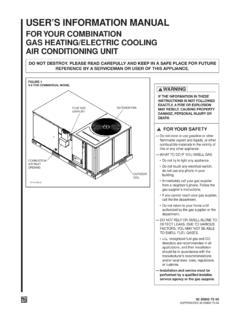
7 Units with damaged cartons shouldbe opened immediately. If damage is found, it should be noted onthe delivery papers, and a damage claim filed with the last carrier. After unit has been delivered to job site, remove carton takingcare not to damage unit. Check the unit rating plate for unit size, electric heat, coil, volt-age, phase, etc. to be sure equipment matches what is re-quired for the job specification. Read the entire INSTRUCTIONS before starting the INSTALLATION . Some building codes require extra cabinet insulation and gas-keting when unit is installed in attic applications. If installed in an unconditioned space, apply caulking aroundthe power wires, control wires, refrigerant tubing and conden-sate line where they enter the cabinet. Seal the power wires onthe inside where they exit conduit opening. Caulking is re-quired to prevent air leakage into and condensate from forminginside the unit, control box, and on electrical controls.
8 Install the unit in such a way as to allow necessary access tothe coil/filter rack and blower/control compartment. Install the unit in accordance with any local code which mayapply and the national codes. Latest editions are availablefrom: National Fire Protection Association, Inc., BatterymarchPark, Quincy, MA 02269. These publications are: ANSI/NFPA No. 70-(Latest Edition) National Electrical Code. NFPA90A INSTALLATION of Air Conditioning and Ventilating Sys-tems. NFPA90B INSTALLATION of warm air heating and air conditioningsystems. The equipment has been evaluated in accordance with theCode of Federal Regulations, Chapter XX, Part 3280. CALIFORNIA RESIDENTS ONLYIMPORTANT: All manufacturer products meet current FederalOSHA Guidelines for safety. California Proposition 65 warningsare required for certain products, which are not covered by theOSHA 's Proposition 65 requires warnings for products sold inCalifornia that contain, or produce, any of over 600 listed chemi-cals known to the State of California to cause cancer or birth de-fects such as fiberglass insulation, lead in brass, and combustionproducts from natural new equipment shipped for sale in California will have labelsstating that the product contains and/or produces Proposition 65chemicals.
9 Although we have not changed our processes, havingthe same label on all our products facilitates manufacturing andshipping. We cannot always know when, or if products will besold in the California may receive inquiries from customers about chemicals foundin, or produced by, some of our heating and air-conditioning equip-ment, or found in natural gas used with some of our below are those chemicals and substances commonly as-sociated with similar equipment in our industry and other manu-facturers. Glass Wool (Fiberglass) Insulation Carbon Monoxide (CO) Formaldehyde BenzeneMore details are available at the Websites for OSHA (Occupa-tional Safety and Health Administration), at theState of California's OEHHA (Office of Environmental Health Haz-ard Assessment), at education is im-portant since the chemicals and substances on the list are foundin our daily lives.
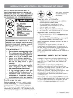
10 Most consumers are aware that products pres-ent safety and health risks, when improperly used, handled INFORMATION (cont.)General Information5 INSTALLATION ChecklistREFER TO INSTALLATION INSTRUCTIONSGAS SUPPLY_____ Correct pipe size (record size)_____ Correct supply pressure (during furnace operation) (record pressure)_____ Manifold pressure (record upstream pressure)_____ No gas leaks_____ Kit Number (if applicable) (record kit number)ELECTRICAL_____ 115 supply (Dedicated Circuit) (record voltage)_____ Polarity observed_____ Furnace properly grounded_____ Correct wire size (record type and gauge)FURNACE INSTALLATION_____ Correct clearance to combustibles (record clearance)_____ Correct clearance for service (at front) (record clearance)DUCT STATIC PRESSURE_____ in. on heating speed (record static pressure)_____ in. on cooling speed (record static pressure)_____ Air temperature rise in heat (record air temperature rise)_____ Air temperature rise in cool (record air temperature rise)VENTING_____ Correct vent pipe diameter and length (according to NFGC tables) _____ Vent connection size_____ Correct venting material (according to NFGC tables)_____ Correct lining for masonry chimneys_____ Adequate clearance from combustibles_____ Proper negative pressure reading in the vent_____ Vent pipe secured to induced draft blower housingCOMBUSTION AIR_____ Proper source of combustion air_____ Correct combustion air opening size_____ Optional attic combustion air pull_____ Non-attic combustion air pullChecklistInstallation INSTRUCTIONS remain with the furnace as a reference guide to the servicing contractor.