Transcription of Interfacing PDM digital microphones using STM32 MCUs and ...
1 July 2019AN5027 Rev 21/661AN5027 Application noteInterfacing PDM digital microphones using STM32 MCUs and MPUsIntroductionDigital MEMS (microelectromechanical systems) microphones target all audio applications where small size, high sound quality, reliability and affordability are key requirements. Their combination of small footprint and noise immunity allows the implementation of multiple microphones in a single device, creating an increasing growth of audio in industrial and consumer applications by offering a hands-free human machine interface, noise cancellation, and high quality audio STM32 32-bit Arm Cortex MCUs and the STM32 Arm Cortex MPUs offer a wide audio capability with a rich connectivity, including serial and enhanced voice-acquisition interfaces allowing the user to easily build solution for microphone-based document targets digital MEMS microphones having a pulse-density modulated (PDM) output and describe how to connect them in mono and stereo configurations to STM32 MCUs and MPUs by using the SPI/I2S, SAI and DFSDM peripherals.
2 It provides guidelines and examples based on STM32 CubeMX and shows how to properly configure the STM32 device to acquire and handle raw data from the microphones in order to transform this raw data into standard data for Rev 2 Contents1 PDM digital microphones overview .. acquisition overview .. digital microphone block diagram .. digital microphones connection .. and PCM signals .. density modulation (PDM) .. code modulation (PCM) .. to PCM conversion .. parameters .. ratio (SNR) .. overload point (AOP) .. supply rejection ratio (PSRR) .. value of digital microphones .. ST digital microphones .. 152 Connecting PDM digital microphones to STM32 MCUs and MPUs .. peripheral interface (SPI) /Inter-IC sound (I2S) .. configuration .. configuration .. audio interface (SAI) .. a single sub-block .. two synchronous SAI sub-blocks .. PDM interface .. filter for sigma delta modulators (DFSDM).
3 Configuration .. considerations .. digital microphone clock .. peripheral clocks .. number considerations .. 313 digital signal processing .. audio software decoding library .. 32AN5027 Rev 23 .. data flow .. signal processing .. filters for digital signal processing .. data flow: acquisition and processing .. 344 Examples of configuration based on STM32 CubeMX .. 1: Interfacing digital microphones in mono or stereo mode with I2S, SPI or a single SAI sub-block .. configuration using STM32 CubeMX .. PDM software decoding library middleware files .. 2: Interfacing digital microphones in stereo mode with SAI using two synchronous sub-blocks .. configuration using STM32 CubeMX .. PDM software decoding library middleware files .. 3: Interfacing digital microphones in stereo mode with SAI using PDM interface .. configuration using STM32 CubeMX .. PDM software decoding library middleware files.
4 4: Interfacing digital microphones using DFSDM .. configuration using STM32 CubeMX .. 585 Conclusion .. 646 Revision history .. 65 List of tablesAN50274/66AN5027 Rev 2 List of tablesTable signal pattern selection .. 9 Table description .. 9 Table value of digital microphone .. 14 Table digital microphones .. 15 Table IO lines versus the number digital microphones to be connected .. 24 Table examples and the associated microphone clock frequency .. 29 Table used to connect one digital microphone.. 31 Table used to connect two digital microphones .. 31 Table used to connect four digital microphones .. 31 Table clock configuration and accuracy .. 36 Table clock configuration and accuracy .. 39 Table configuration and accuracy .. 42 Table clock configuration and accuracy .. 49 Table filter order values .. 60 Table clock configuration accuracy values .. 63 Table revision history.
5 65AN5027 Rev 25/66AN5027 List of figures6 List of figuresFigure of sound acquisition in audio application .. 7 Figure PDM digital MEMS microphone block diagram .. 8 Figure configuration - Generating data on right channel .. 9 Figure channel data pattern .. 10 Figure configuration - Generating data on left channel .. 10 Figure channel data pattern .. 10 Figure configuration: Sharing one data line .. 11 Figure configuration data pattern .. 11 Figure signal .. 12 Figure signal .. 13 Figure one digital microphone to SPI or I2S in mono configuration .. 17 Figure two digital microphone to SPI block in stereo configuration .. 18 Figure mode timing diagram.. 19 Figure one digital microphone to SAI in mono configuration .. 20 Figure two digital microphones to SAI in stereo configuration using a SAI sub-block and a timer .. 22 Figure two digital microphone to SAI in stereo configuration using two synchronous SAI sub-blocks.
6 23 Figure interface capability on Interfacing up to four microphone pairs .. 25 Figure format when using the SAI PDM interface with a slot size of 32 bits, and 8 microphones .. 26 Figure format when using the SAI PDM interface with a slot size of 8 bits, and 8 microphones .. 26 Figure capability to interface up to 4 digital microphones .. 27 Figure configuration .. 28 Figure and kernel clock topology for SPI .. 30 Figure and kernel clock topology for SAI and DFSDM .. 30 Figure data acquisition and processing (block diagram).. 33 Figure signal processing .. 33 Figure data acquisition and processing using DFSDM (block diagram) .. 34 Figure GPIO pin configuration .. 36 Figure clock configuration .. 37 Figure configuration .. 37 Figure parameter settings .. 38 Figure DMA settings .. 38 Figure GPIO and pin configuration .. 39 Figure clock configuration .. 39 Figure configuration .. 40 Figure parameter setting.
7 40 Figure DMA settings .. 41 Figure GPIO and pin configuration .. 41 Figure clock configuration at 16 kHz for mono mode .. 42 Figure configuration .. 43 Figure parameter setting .. 44 Figure DMA settings .. 45 Figure request settings .. 45 Figure GPIO and pin configuration .. 46 Figure configuration .. 46 List of figuresAN50276/66AN5027 Rev 2 Figure parameter settings .. 47 Figure GPIO and pin configuration .. 48 Figure clock configuration .. 49 Figure parameter settings .. 51 Figure parameter settings .. 52 Figure DMA settings .. 52 Figure GPIO and pin configuration .. 53 Figure clock configuration for 2 microphones at 16 kHz .. 54 Figure configuration .. 54 Figure parameter settings .. 55 Figure DMA settings .. 56 Figure configuration .. 56 Figure M7 parameter settings .. 57 Figure GPIO configuration in stereo mode.. 58 Figure pin configuration .. 59 Figure Channel 1 configuration.
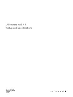
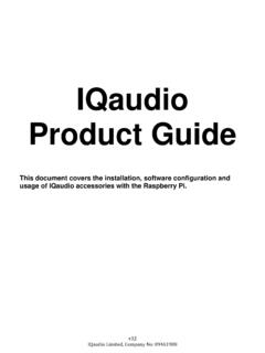
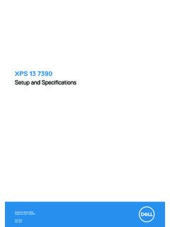
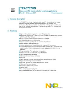
8 59 Figure Channel 0 configuration .. 60 Figure Filter 0 configuration .. 61 Figure Filter 1 configuration .. 61 Figure output clock configuration .. 62 Figure DMA setting .. 62 Figure clock configuration .. 63AN5027 Rev 27/66AN5027 PDM digital microphones overview641 PDM digital microphones overviewThis section provides a brief description of PDM digital microphones and presents basic cases of Interfacing them with STM32 devices. STM32 MCUs and MPUs are Arm (a) based devices. Sound acquisition overviewThe digital MEMS microphone is a sensor that convert acoustic pressure waves into a digital signal. The STM32 MCUs and MPUs acquire digital data from the microphone(s) through particular peripherals to be processed and transformed into data standard for audio . The audio data is then handled by the microcontroller according to the targeted audio 1. Example of sound acquisition in audio applicationa. Arm is a registered trademark of Arm Limited (or its subsidiaries) in the US and/or acquisition and processingSound acquisition audio applicationVoice recognitionHigh quality audio recordNoise cancellationDigital MEMS MicrophoneSound waveSTM32 MCUMS47180V1 PDM digital microphones overviewAN50278/66AN5027 Rev PDM digital microphone block diagramThe main parts in a digital microphone are a MEMS transducer, an amplifier and a PDM 2.
9 Typical PDM digital MEMS microphone block diagramMEMS transducerThe MEMS transducer is a variable capacitance that converts the change into air pressure caused by sound waves to a amplifier buffers the voltage provided by the MEMS transducer, and provides a sufficiently strong signal to the PDM modulatorPDM modulator converts the buffered analog signal into a serial pulse density modulated signal. The clock input (CLK) is used to control the PDM modulator. The clock frequency range for ST digital microphones is from 1 MHz to MHz. This frequency defines the sampling rate at which the amplifier s analog output signal is sampled to produce a discrete-time representation (PDM bitstream).Channel selectThe microphone s output is driven to the proper level on a selected clock edge and then goes into a high impedance state for the other half of the clock cycle. The channel select defines the clock edge on which the digital microphone outputs valid data.
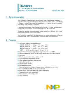
10 The LR pin must be connected to Vdd or b l e 1 shows how to select the DOUT signal Rev 29/66AN5027 PDM digital microphones overview64 PowerPower delivers Vdd and GND supplies to the different digital microphone s components. The power supply should be properly provided to the microphone since any ripple can generate noise on the description Basic digital microphones connectionMono modeIn this mode the LR pin can be either connected to Vdd or to pin is connected to VddFigure 3. Mono configuration - Generating data on right channelOn the rising edge of the clock, the microphone generates valid data for half of the clock period, then goes into a high impedance state for the other 1. DOUT signal pattern selection LRDOUTCLK lowCLK highGNDV alid dataHigh impedanceVddHigh impedanceValid dataTable 2. Pin description Pin V power supplyInputGND0 VInputLRLeft/right selectionInputCLKS ynchronization clockInputDOUTLeft/righ PDM data outputOutputCLOCK OUTPUTVddLRDOUTCLKSTM32 DATADATA INPUTMS47148V1 PDM digital microphones overviewAN502710/66AN5027 Rev 2 Figure 4.