Transcription of K1010 Series - cosmo-ic.com
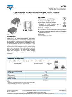
1 K1010 Series 4 PIN phototransistor . cosmo PHOTOCOUPLER. Description Schematic The K1010 Series consist of an infrared emitting diode, optically coupled to a phototransistor detector. They are packaged in a 4-pin DIP package and available in wide-lead spacing and SMD option. 1. Anode 2. Cathode 3. Emitter 4. Collector Features 1. Current transfer ratio ( CTR Min. 50% at IF=5mA VCE=5V ). 2. High isolation voltage between input and output ( Viso 5000 Vrms ). 3. Pb free and RoHS compliant 4. MSL class 1. 5. Agency Approvals UL Approved (No. E169586): UL1577. c-UL Approved (No. E169586). VDE Approved (No. 101347): DIN EN60747-5-5. FIMKO Approved: EN60065, EN60950, EN60335. SEMKO Approved: EN60065, EN60950, EN60335. CQC Approved: GB8898-2011, Applications System appliances Measuring instruments Computer terminals Programmable controllers Medical instruments Physical and chemical equipment Signal transmission between circuits of different potentials and impedances Cosmo Electronics Corp.
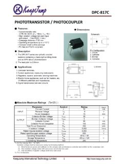
2 Document No. -1- K1010 Series 4 PIN phototransistor . cosmo PHOTOCOUPLER. Outside Dimension Unit : mm type. mount type. K10101X K10104X. 0~10 .. creepage distance type creepage distance for surface mount type. K10103X K10106X. 0~10 . + TOLERANCE Device Marking Notes: cosmo 1010 cosmo 817 1010. YWW 817. YWW Y: Year code / WW: Week code : CTR rank Cosmo Electronics Corp. Document No. -2- K1010 Series 4 PIN phototransistor . cosmo PHOTOCOUPLER. Absolute Maximum Ratings (Ta=25 ). Parameter Symbol Rating Unit Forward current IF 50 mA. Peak forward current IFM 1 A. Input Reverse voltage VR 6 V. Power dissipation PD 70 mW. Collector-emitter voltage VCEO 80 V. Emitter-collector voltage VECO 6 V. Output Collector current IC 50 mA. Collector power dissipation PC 150 mW.
3 Total power dissipation Ptot 200 mW. Isolation voltage 1 minute Viso 5000 Vrms Operating temperature Topr -55 to +115 . Storage temperature Tstg -55 to +125 . Soldering temperature 10 seconds Tsol 260 . Electro-optical Characteristics (Ta=25 ). Parameter Symbol Conditions Min. Typ. Max. Unit Forward voltage VF IF=20mA - V. Peak forward voltage VFM IFM= - - V. Input Reverse current IR VR=4V - - 10 A. Terminal capacitance Ct V=0, f=1 KHz - 30 - pF. Output Collector dark current ICEO VCE=20V, IF=0 - - A. IF=5mA, VCE=5V 50 - 600. Current transfer ratio CTR %. IF=1mA, VCE=5V 15 - - Collector-emitter saturation VCE(sat) IF=20mA, IC=1mA - V. 10 11. Transfer Isolation resistance Riso DC500V 5x10 10 - . charac- teristics Floating capacitance Cf V=0, f=1 MHz - pF.
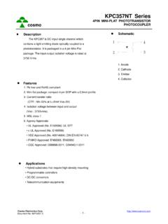
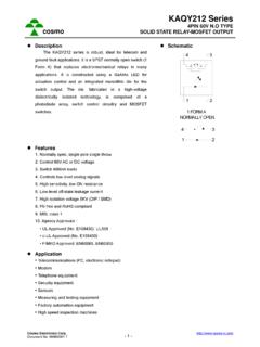
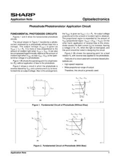
4 Cut-off frequency fC VCC=5V, IC=2mA, RL=100 - 80 - KHz Response time (Rise) tr - 4 18 s VCE=2V, IC=2mA, RL=100 . Response time (Fall) tf - 3 18 s Cosmo Electronics Corp. Document No. -3- K1010 Series 4 PIN phototransistor . cosmo PHOTOCOUPLER. Current Transfer Ratio vs. Forward Current 500. Classification table of current V CE =5V. 450 Ta=25 . transfer ratio is shown below. Current Transfer Ratio 400. Marking of 350. K1010 Model No. CTR ( % ). Classification CTR ( % ). 300. K1010 A 80 ~ 160 A 250. K1010 B 130 ~ 260 B 200. K1010 C 200 ~ 400 C. 150. K1010 D 300 ~ 600 D. 100. K1010 E 50 ~ 600 Blank,A,B,C,D,E. 50. 0. 0 1 2 5 10 20 50. Forward Current IF (mA). Collector Power Dissipation Collector Dark Current vs. Ambient Temperature vs. Ambient Temperature -5.
5 250 10. VCE=20V. Collector Power Dissipation 10-6. Collector Dark Current 200. -7. 10. PC ( mW ). 150. ICEO ( A ). -8. 10. 100 -9. 10. -10. 50 10. -11. 0 10. -55 0 25 50 75 115 125 -55 0 25 50 75 115. Ambient Temperature Ta ( ) Ambient Temperature Ta ( ). Forward Current Forward Current vs. Ambient Temperature vs. Forward Voltage 60 500. Ta=75 C. Forward Current IF ( mA ). Forward Current IF ( mA ). 50 200. 50 C 25 C. 40 100. 50. 30 0 C. 20. -25 C. 20 10. 5. 10. 2. 0 1. -55 0 25 50 75 115 125 Ambient Temperature Ta ( ) Forward Voltage VF (V). Cosmo Electronics Corp. Document No. -4- K1010 Series 4 PIN phototransistor . cosmo PHOTOCOUPLER. Collector Current Relative Current Transfer Ratio vs. Collector-Emitter Voltage vs. Ambient Temperature 30. 150. IF =30mA Ta=25 C.
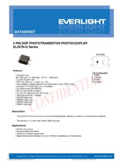
6 20mA IF =5mA. Relative Current Transfer Collector Current IC (mA). 25 VCE=5V. 20 100. Ratio ( % ). 15 10mA. 10 50. 5mA. 5. 0 0. 0 1 2 3 4 5 6 7 8 9 -55 -25 0 25 50 75 115. Collector-Emitter Voltage VCE (V) Ambient Temperature Ta ( ). Collector-Emitter Saturation Voltage Collector-Emitter Saturation vs. Ambient Temperature Voltage vs. Forward Current 7. IF =20mA Ta=25 C. Collector-Emitter Saturation Collector-Emitter Saturation Ic=1mA 6. Ic= Voltage VCE ( V ). Voltage VCE ( V ). 5. Ic=1mA. 4. Ic=3mA. 3. Ic=5mA. 2. Ic=7mA. 1. 0 0. -55 0 25 50 75 115 0 5 10. Ambient Temperature Ta ( ) Forward Current IF (mA). Response Time (Rise) Response Time (Fall). vs. Load Resistance vs. Load Resistance 100 100. VCE =2V VCE =2V. Ic=2mA. Response Rise Time ( us ). Response Fall Time ( us ).
7 50 50 Ic=2mA. Ta=25 C Ta=25 C. tr 20 20 tf 10 10. 5 5. 2 2. 1 1. 1 10 1 10. Load Resistance RL (K ) Load Resistance RL (K ). Cosmo Electronics Corp. Document No. -5- K1010 Series 4 PIN phototransistor . cosmo PHOTOCOUPLER. Test Circuit for Response Time Vcc RL. IF Vce IF. 1 4. Vce 2 3 90%. 10%. tr tf Cosmo Electronics Corp. Document No. -6- K1010 Series 4 PIN phototransistor . cosmo PHOTOCOUPLER. Recommended Soldering Conditions (a) Infrared reflow soldering . Peak reflow soldering 260 or below (package surface temperature). Time of peak reflow temperature 10 sec Time of temperature higher than 230 30-60 sec Time to preheat temperature from 180~190 60-120 sec Time(s) of reflow Two Flux Rosin flux containing small amount of chlorine (The flux with a maximum chlorine content of Wt% is recommended.)
8 Recommended Temperature Profile of Infrared Reflow 10 sec Max. 260 . temperature 230 . 190 . 30-60 sec 180 . 60-120 sec t (s). (b) Wave soldering . Temperature 260 or below (molten solder temperature). Time 10 seconds or less Preheating conditions 120 or below (package surface temperature). Time(s) of reflow One Flux Rosin flux containing small amount of chlorine (The flux with a maximum chlorine content of Wt% is recommended.). (c) Cautions . Fluxes Avoid removing the residual flux with freon-based and chlorine-based cleaning solvent. Avoid shorting between portion of frame and leads. Cosmo Electronics Corp. Document No. -7- K1010 Series 4 PIN phototransistor . cosmo PHOTOCOUPLER. Numbering System K1010 X Y (Z). Notes: K1010 = Part No. X = Lead form option (1,3,4,6).
9 Y = CTR rank option (A ~ E). Z = Tape and reel option (TLD, TRU). Option Description Packing quantity 4 (TLD) surface mount type package + TLD tape & reel option 2000 units per reel 4 (TRU) surface mount type package + TRU tape & reel option 2000 units per reel long creepage distance for surface mount type package +. 6 (TLD) 2000 units per reel TLD tape & reel option long creepage distance for surface mount type package +. 6 (TRU) 2000 units per reel TRU tape & reel option Recommended Pad Layout for Surface Mount Lead Form mount type. creepage distance for surface mount type. 4 pin SMD 4 pin L. Unit : mm Cosmo Electronics Corp. Document No. -8- K1010 Series 4 PIN phototransistor . cosmo PHOTOCOUPLER. 4-pin SMD Carrier Tape & Reel TOLERANCE Cosmo Electronics Corp.
10 Document No. -9- K1010 Series 4 PIN phototransistor . cosmo PHOTOCOUPLER. 4-pin L Carrier Tape & Reel . TOLERANCE Cosmo Electronics Corp. Document No. - 10 - K1010 Series 4 PIN phototransistor . cosmo PHOTOCOUPLER. Application Notice The content of datasheet is the guidance for product use only. cosmo takes no responsibility to the accuracy of the information provided here. For continuously improving all of products, including quality, reliability, , cosmo reserves the right to change the specification, characteristics, data, materials, and structure of products without notice. Please contact with cosmo to obtain the latest specification. It would be required to comply with the absolute maximum ratings listed in the specification. cosmo has no liability and responsibility to the damage caused by improper use of the products.