Example: stock market
L~ N 1 ! ~- v=V02 - TI.com
Figure 6 shows the operation of the mag amp core as it switches from saturation (point 1) to reset (point 2) and back to saturation.
Information
Domain:
Source:
Link to this page:
Documents from same domain

LM136-2.5,LM236-2.5,LM336-2 - TI.com
www.ti.comLM136-2.5/LM236-2.5/LM336-2.5V Reference Diode General Description The LM136-2.5/LM236-2.5 and LM336-2.5 integrated cir-cuits are …

SimpleLink™ CC3120, CC3220 Wi-Fi ... - Texas …
www.ti.comUser User x x x x x x x x x x x x x x x x x x x x Application Servers Vendor IoT Devices Internet Introduction www.ti.com 4 SWRA509A–February 2017–Revised March 2017 Submit Documentation Feedback

www.ti.com SNVS749F - Texas Instruments
www.ti.comLM136-2.5-N SNVS749F – MAY 1998– REVISED APRIL 2013 www.ti.com Typical Performance Characteristics (continued) Temperature Drift Figure 13. …

MSP430x2xx Family User's Guide (Rev. J) - TI.com
www.ti.comMSP430x2xx Family User's Guide Literature Number: SLAU144J December 2004– Revised July 2013

1.8-V Micropower CMOS Operational Amplifier …
www.ti.com5 OPA2333-HT www.ti.com SBOS483I –JULY 2009–REVISED MAY 2015 Product Folder Links: OPA2333-HT Copyright © 2009–2015, Texas Instruments Incorporated Submit Documentation Feedback

LMC6482 CMOS Dual Rail-To-Rail Input and Output ...
www.ti.comLMC6482 www.ti.com SNOS674E –NOVEMBER 1997–REVISED APRIL 2015 5 Pin Configuration and Functions D, DGK and P Packages 8-Pin SOIC, VSSOP and PDIP (Top View) Pin Functions PIN TYPE DESCRIPTION NO.

OPAx354 250-MHz, Rail-to-Rail I/O, CMOS …
www.ti.comOPA354 IN +IN V OUT V+ V Product Folder Order Now Technical Documents Tools & Software Support & Community Reference Design An IMPORTANT NOTICE at the end of this data sheet addresses availability, warranty, changes, use …

Analog linearization of resistance temperature …
www.ti.com21 Analog Applications Journal Texas Instruments Incorporated 4Q 2011 www.ti.com/aaj High-Performance Analog Products …

TMS320C28x DSP/BIOS 5.x Application …
www.ti.comSPRU625L—August 2012 API Functional Overview 9 Submit Documentation Feedback www.ti.com Naming Conventions 1.2 Naming Conventions The format for a DSP/BIOS operation name is a 3- or 4-letter prefix for the module that contains the

WL18x7MOD WiLink™ 8 Dual-Band Industrial …
www.ti.comProduct Folder Order Now Technical Documents Tools & Software Support & Community Reference Design An IMPORTANT NOTICE at the end of this data sheet addresses availability, warranty, changes, use in safety-critical applications,
Related documents
Auto Switch Guide - SMC ETech
content2.smcetech.com6-19 Contact Protection Box/CD-P11, CD-P12 Prior to Use Auto Switch Hysteresis/Contact Protection Box Auto Switch Hysteresis The distance between the turn-on point (ON) of the switch by mov-

Chapter 8 Introduction to Magnetic Fields - MIT
web.mit.eduwhere a and b represent the endpoints of the wire. As an example, consider a curved wire carrying a current I in a uniform magnetic field B G, as shown in Figure 8.3.4. Figure 8.3.4 A curved wire carrying a current I. Using Eq. (8.3.3), the magnetic force on the wire is given by

SERIES 8000 TYPE 02, 03 & 04 REED SWITCH Wiring Diagram
www.starcyl.comSERIES 8000 TYPE 02, 03 & 04 REED SWITCH Wiring Diagram **Minimum Gauss rating required for proper operation; as measured on sensor surface *Size of sensing area depends upon size and strength of magnet and thickness of cylinder wall

INSTALLATION INSTRUCTIONS E600 SERIES MAGNETIC LOCK
www.sdcsecurity.com801 Avenida Acaso, Camarillo, Ca. 93012 (805) 494-0622 • Fax: (805) 494-8861 www.sdcsecurity.com • E-mail: service@sdcsecurity.com The E600 Series magnetic lock is mounted to the underside of the header, on the stop side of the
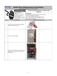
Switch Base Replacement Instructions - eaton.com
www.eaton.comStep Work Description 1 Turn OFF and lock out all power supplying this switch before installing base kit. 2 Turn switch to "OFF" position. 3 Verify there is NO voltage present at the line and
MAGNETIC MOTOR STARTERS AND MAGNETIC …
www.mitsubishielectric.comIncorporation of CAN terminal for simple wiring Unified design for N series The design has been unified for the MS-N series. The front face of the product is a bright white color, making the