Transcription of LM3405A 1.6-MHz, 1-A Constant Current Buck LED Driver …
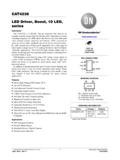
1 LM3405 AVIN VIN EN/DIMBOOSTSWFBGNDC3L1C2 R1 D1 C1 IF ONOFFC4 VOUT D2D3 Copyright 2016, texas instruments IncorporatedProductFolderSample &BuyTechnicalDocumentsTools &SoftwareSupport &CommunityAn IMPORTANTNOTICEat the end of this datasheetaddressesavailability,warranty, changes,use in safety-criticalapplications,intellectual propertymattersand OCTOBER2007 ,1-A ConstantCurrentBuck LED DriverWith InternalCompensationinTiny SOT and MSOP-PowerPAD Packages11 Features1 VINO peratingRangeof 3 V to 22 V Drivesup to 5 High-BrightnessLEDsin Seriesat1 A ThinSOT-6and MSOP-PowerPAD -8 Packages EN/DIMI nputfor Enablingand PWMD immingofLEDs 300-m NMOSS witch 40-nAShutdownCurrentat VIN= 5 V InternallyCompensatedCurrent-modeControl Cycle-by-CycleCurrentLimit InputVoltageUVLO OvercurrentProtection ThermalShutdown2 Applications LEDD rivers ConstantCurrentSources IndustrialLighting LEDF lashlights LEDL ightbulbs3 DescriptionTheLM3405 Ais a 1-A constantcurrentbuckLEDdriverdesignedto providea simple,highefficiencysolutionfor minimizepowerdissipation,an externalresistorsetsthe currentasneededfor drivingvarioustypesof internallyset to MHz,allowingsmallsurfacemountinductorsan d capacitorsto be LM3405 Ausescurrent-modecontroland internalcompensationofferingeaseof use and predictable.
2 Highperformanceregulationovera maximuminputvoltageof 22 V, the devicecan driveup to 5 High-BrightnessLEDsin seriesat 1-A forwardcurrent,with the singleLEDforwardvoltageof for enablingand PWMdimmingof LEDs,thermalshutdown,cycle-by-cyclecurre ntlimit and (1)PARTNUMBERPACKAGEBODYSIZE(NOM)LM3405 ASOT(6) (8) (1) For all availablepackages,see the orderableaddendumatthe end of the LEDC urrent(VIN= 12 V)2LM3405 ASNVS508D OCTOBER2007 :LM3405 ASubmitDocumentationFeedbackCopyright 2007 2016,TexasInstrumentsIncorporatedTableof Contents1 Pin Configurationand Applicationand Deviceand Mechanical,Packaging,and RevisionHistoryNOTE:Pagenumbersfor previousrevisionsmay differfrompagenumbersin the (May2013)to RevisionDPage AddedESDR atingstable,FeatureDescriptionsection,De viceFunctionalModes,Applicationand Implementationsection,PowerSupplyRecomme ndationssection,Layoutsection,Deviceand DocumentationSupportsection,andMechanica l,Packaging,and ChangedR JAfor SOTpackagefrom118 C/Wto ChangedR JAfor MSOP packagefrom73 C/Wto (April2013)to RevisionCPage Changedlayoutof NationalSemiconductorDataSheetto TI OCTOBER2007 REVISEDSEPTEMBER2016 ProductFolderLinks:LM3405 ASubmitDocumentationFeedbackCopyright 2007 2016,TexasInstrumentsIncorporated5 Pin Configurationand FunctionsDDCP ackage6-PinSOTTop ViewDGNP ackage8-PinMSOP-PowerPAD Top ViewPin FunctionsPINI/ODESCRIPTIONNAMESOTMSOP-Po werPADBOOST14 OBoostvoltagethat drivesthe bootstrapcapacitorisconnectedbetweenthe BOOSTand SW , 7 Signaland powergroundpin.
3 Placethe bottomresistorof the feedbacknetworkas closeas possibleto this ConnectFB to the LEDstringcathodeand an externalresistorto groundto set the pin with aperiodiclogicsquarewaveof varyingduty cycleat differentfrequenciescontrolsthe brightnessof not allowthis pin to float or be greaterthanVIN+ bypasscapacitorlocallyfromthis pin to Connectthis pin to the inductor,catchdiode,and 3 No Attachto powergroundpin (GND).4LM3405 ASNVS508D OCTOBER2007 :LM3405 ASubmitDocumentationFeedbackCopyright 2007 2016,TexasInstrumentsIncorporated(1)Stre ssesbeyondthoselistedunderAbsoluteMaximu mRatingsmay causepermanentdamageto the stressratingsonly,whichdo not implyfunctionaloperationof the deviceat theseor any otherconditionsbeyondthoseindicatedunder RecommendedOperatingConditions. Exposureto absolute-maximum-ratedconditionsfor extendedperiodsmay (unlessotherwisenoted)(1)MINMAXUNITVIN voltage SW voltage voltage (VIN+ )VJunctiontemperature,TJ150 CStoragetemperature,Tstg 65150 C(1)JEDEC documentJEP155statesthat 500-VHBM allowssafe manufacturingwith a standardESDcontrolprocess.
4 (2)JEDEC documentJEP157statesthat 250-VCDM allowssafe manufacturingwith a SOTPACKAGEV(ESD)ElectrostaticdischargeHu man-bodymodel(HBM),per ANSI/ESDA/JEDECJS-001(1) 2000 VCharged-devicemodel(CDM),per JEDEC specificationJESD22-C101(2) 1000LM3405 AIN MSOP-PowerPADPACKAGEV(ESD)Electrostaticd ischargeCharged-devicemodel(CDM),per JEDEC specificationJESD22-C101(2) (VIN+ )VBoostto SW 40125 OCTOBER2007 REVISEDSEPTEMBER2016 ProductFolderLinks:LM3405 ASubmitDocumentationFeedbackCopyright 2007 2016,TexasInstrumentsIncorporated(1)For moreinformationabouttraditionaland new thermalmetrics,see theSemiconductorand IC (1)LM3405 AUNITDDC(SOT)DGN(MSOP-PowerPAD)6 PINS8 PINSR C/WR JC(top)Junction-to-case(top) C/WR C/W C/W C/WR JC(bot)Junction-to-case(bottom)thermalre sistanceN/A8 ,VIN= 12 V. TYPvaluesare for TJ= 25 C only;MIN/MAXlimitsapplyoverthe junctiontemperature(TJ) rangeof 40 C to 125 C. Typicalvaluesrepresentthe mostlikelyparametricnorm,and are VFB/( VINxVFB)FeedbackvoltagelineregulationVIN = 3 V to 22 cycleVFB= 0 V85%94%RDS(ON)SwitchON resistanceSOT(VBOOST- VSW= 3 V)300600m MSOP-PowerPAD(VBOOST- VSW= 3 V)360700 ICLS witchcurrentlimitVBOOST- VSW= 3 V, VIN= 3 ,VFB= (shutdown)VEN/DIM= 0 AVEN/DIM_ AISWS witchleakageVIN= 22 A6LM3405 ASNVS508D OCTOBER2007 :LM3405 ASubmitDocumentationFeedbackCopyright 2007 2016, ,VIN= 12 V, VBOOST VSW= 5 V and TA= 25 5 VFigure1.
5 Efficiencyvs LEDC urrentIF= 1 AFigure2. Efficiencyvs InputVoltageIF= AFigure3. Efficiencyvs InputVoltageIF= Efficiencyvs InputVoltageFigure5. VFBvs TemperatureFigure6. OscillatorFrequencyvs OCTOBER2007 REVISEDSEPTEMBER2016 ProductFolderLinks:LM3405 ASubmitDocumentationFeedbackCopyright 2007 2016,TexasInstrumentsIncorporatedTypical Characteristics(continued)Unlessotherwis especified,VIN= 12 V, VBOOST VSW= 5 V and TA= 25 CurrentLimitvs TemperatureVBOOST- VSW= 3 VFigure8. SOTRDS(ON)vs TemperatureFigure9. QuiescentCurrentvs TemperatureVIN= 15 VIF= AFigure10. Start-UpResponseto EN/DIMS ignal00 VIN-VD1 TONttInductorCurrentD = TON/TSWVSWTOFFTSWILSWV oltage'iLIFILPK8LM3405 ASNVS508D OCTOBER2007 :LM3405 ASubmitDocumentationFeedbackCopyright 2007 2016,TexasInstrumentsIncorporated7 LM3405 Ais a PWM, Current -modecontrolledbuckswitchingr egulatordesignedto providea simple,highefficiencysolutionfor drivingLEDswith a presetswitchingfrequencyof operatewith smallsurfacemountcapacitorsand inductors,resultingin LEDdriversthat needonly aminimumamountof LM3405 Ais internallycompensated,simpleto use,and followingdescriptionof operationof the LM3405 Arefersto theTypicalApplicationCircuitand to the waveformsin Figure11.
6 The LM3405 Asuppliesa regulatedoutputcurrentby switchingthe internalNMOS powerswitchat constantfrequencyand switchingcyclebeginsat the fallingedgeof the resetpulsegeneratedby the pulsegoeslow, theoutputcontrollogicturnson the on-time,the SW pin voltage(VSW)swingsup to approximatelyVIN, and the inductorcurrent(IL) increaseswith a measuredby thecurrentsenseamplifier,whichgeneratesa n outputproportionalto the the regulator s correctiverampand comparedto the erroramplifier s output,whichis proportionalto the differencebetweenthe feedbackvoltageand VREF. Whenthe PWMcomparatoroutputgoeshigh,theinternalp owerswitchturnsoff until the switchoff-time,inductorcurrentdischarges throughthe catchdiodeD1, whichforcesthe SW pin to swingbelowgroundby the forwardvoltage(VD1) of the regulatorloopadjuststhe dutycycle(D) to maintaina constantoutputcurrent(IF)throughthe LED,by forcingFB pin voltageto be equalto VREF( ).Figure11. SW Pin Voltageand InductorCurrentWaveformsof LM3405 ACopyright 2016, texas instruments OCTOBER2007 REVISEDSEPTEMBER2016 ProductFolderLinks:LM3405 ASubmitDocumentationFeedbackCopyright 2007 2016, and diodeD2 in theFunctionalBlockDiagramare usedto generatea voltageVBOOST.
7 The voltageacrossC3, VBOOST- VSW, is the gatedrivevoltageto the properlydrivetheinternalNMOS switchduringits on-time,VBOOST needsto be at A largevalueofVBOOST- VSWis recommendedto achievebetterefficiencyby minimizingboththe internalswitchON resistance(RDS(ON)), and the switchrise and fall ,VBOOST- VSWshouldnot exceedthe maximumoperatinglimit of LM3405 Astartsup, internalcircuitryfromVINsuppliesa 20-mAcurrentto the BOOSTpin, flowingoutof the BOOSTpin into C3. This currentchargesC3 to a voltagesufficientto turn the switchon. The boost pinwill continueto sourcecurrentto C3 until the voltageat the feedbackpin is greaterthan123 variousmethodsto deriveVBOOST:1. Fromthe inputvoltage(VIN)2. Fromthe outputvoltage(VOUT)3. Froma shuntor seriesZenerdiode4. Froman externaldistributedvoltagerail (VEXT)The first methodis shownin theFunctionalBlockDiagram. CapacitorC3 is chargedvia diodeD2 by VIN. Duringa normalswitchingcycle,whenthe internalNMOS powerswitchis off (TOFF) (seeFigure11), VBOOST equalsVINminusthe forwardvoltageof D2 (VD2), duringwhichthe currentin the inductor(L1) forwardbiasesthe catchdiodeD1 (VD1).
8 Thereforethe gatedrivevoltagestoredacrossC3 is:VBOOST- VSW= VIN- VD2+ VD1(1)Whenthe NMOS switchturnson (TON), the switchpin risesto:VSW= VIN (RDS(ON) IL)(2)Copyright 2016, texas instruments IncorporatedCopyright 2016, texas instruments Incorporated10LM3405 ASNVS508D OCTOBER2007 :LM3405 ASubmitDocumentationFeedbackCopyright 2007 2016,TexasInstrumentsIncorporatedFeature Description(continued)Sincethe voltageacrossC3 remainsunchanged,VBOOSTis forcedto rise thus reversebiasingD2. The voltageatVBOOSTis then:VBOOST= 2 VIN (RDS(ON) IL) VD2+ VD1(3)Dependingon the qualityof the diodesD1 and D2, the gatedrivevoltagein this methodcan be slightlyless orlargerthanthe inputvoltageVIN. For bestperformance,ensurethat the variationof the inputsupplydoesnotcausethe gatedrivevoltageto fall outsidethe < VIN- VD2+ VD1< V(4)The secondmethodfor derivingthe boostvoltageis to connectD2 to the outputas shownin Figure12. The gatedrivevoltagein this configurationis:VBOOST- VSW= VOUT VD2+ VD1(5)Sincethe gatedrivevoltageneedsto be in the rangeof V to V, the outputvoltageVOUT shouldbe limitedto a the calculationof VOUT, VBOOSTD erivedfromVOUTThe thirdmethodcan be usedin the applicationswherebothVINand VOUTare V.
9 In thesecases,C3 cannotbe chargeddirectlyfromthesevoltages;instead C3 can be chargedfromVINor VOUT minusaZenervoltage(VD3) by placinga ZenerdiodeD3 in serieswith D2 as shownin Figure13. Whenusinga seriesZenerdiodefromthe input,the gatedrivevoltageis VIN- VD3- VD2+ VBOOSTD erivedfromVINT hrougha SeriesZenerCopyright 2016, texas instruments OCTOBER2007 REVISEDSEPTEMBER2016 ProductFolderLinks:LM3405 ASubmitDocumentationFeedbackCopyright 2007 2016,TexasInstrumentsIncorporatedFeature Description(continued)An alternatemethodis to placethe zenerdiodeD3 in a shuntconfigurationas shownin Figure14. A small350mW to 500 mW, a SOTor SODpackagecan be usedfor this smallceramiccapacitorsuchas a V, F capacitor(C5)shouldbe placedin parallelwiththe internalNMOS switchturnson, a pulseof currentis drawnto chargethe Fparallelshuntcapacitorensuresthat the VBOOST voltageis maintainedduringthis shouldbechosento provideenoughRMScurrentto the zenerdiodeand to the BOOSTpin. A recommendedchoicefor thezenercurrent(IZENER) is 1 mA.
10 The currentIBOOST into the BOOSTpin suppliesthe gatecurrentof the reachesa maximumof mA at the highestgatedrivevoltageof V the worstcaseIBOOST, increasethe currentby 50%.In that case,the maximumboostcurrentwill be:IBOOST-MAX= mA = mA(6)R2 will thenbe givenby:R2 = (VIN- VZENER) / (IBOOST_MAX+ IZENER)(7)For example,let VIN= 12 V, VZENER= 5V, IZENER= 1 mA, then:R2 = (12 V 5 V) / ( mA + 1 mA) = (8)Figure14. VBOOSTD erivedfromVINT hrougha ShuntZenerThe fourthmethodcan be usedin an applicationwhichhas an externallow voltagerail, VEXT. C3 can be chargedthroughD2 fromVEXT, independentof VINand bestperformance,ensurethat thegatedrivevoltage,VEXT- VD2+ VD1, falls in the rangeof V to LEDC urrentLM3405 Ais a LEDsare connectedbetweenVOUTand the FB pin as shownin theTypicalApplicationCircuit. The FB pin is at regulationand thereforethe LEDcurrentIFis set by VFBand resistorR1 fromFB to groundby the followingequation:IF= VFB/ R1(9)IFshouldnot exceedthe 1-A currentcapabilityof LM3405 Aand thereforeR1 minimummustbe.