Transcription of LM5034 High Voltage Dual Interleaved Current …
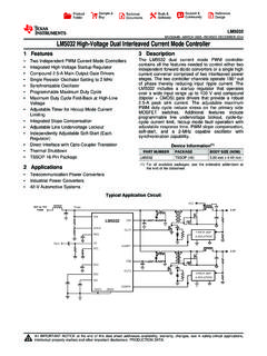
1 ERROR AMP& ISOLATIONERROR AMP& to FEBRUARY2005 REVISEDAPRIL2013LM5034 HighVoltageDualInterleavedCurrentModeCon trollerwithActiveClampCheckforSamples:LM 50341 FEATURESAPPLICATIONS2 TwoIndependentPWMC urrentMode TelecommunicationPowerConvertersControll ers IndustrialPowerConverters IntegratedHighVoltageStartupRegulator +42 VAutomotiveSystems SingleResistorOscillatorSettingto2 MHzTheLM5034dualcurrentmodePWMcontroller SynchronizableOscillatorcontainsallthefe aturesneededtocontroleithertwo ActiveClampGateDriverforP-Channelindepen dentforward/ AdjustableGateDriveOverlapTimechannelsop erate180 outofphasetherebyreducing startup MaximumDutyCycleFold-BackatHighLineregul atorthatoperatesovera wideinputrangeuptoVoltage100 Vandcompound(bipolar+ CMOS) AdjustableTimerforHiccupModeCurrentadjus tabledead-timeoftheactiveclampgatedriver sLimitingandadjustablemaximumPWMdutycycl ereduce IntegratedSlopeCompensationstressonthepr imarysideMOSFET switches.
2 AdjustableLineUnder-VoltageLockoutAdditi onalfeaturesincludeprogrammablelineunder -voltagelockout,cycle-by-cyclecurrentlim it,hiccup IndependentlyAdjustableSoft-Start(Eachmo defaultoperationwithadjustablerestartdel ay,Regulator)PWMslopecompensation,soft-s tart,anda 2 MHz DirectInterfacewithOpto-CouplerTransisto rcapableoscillatorwithsynchronizationcap ability. ThermalShutdownPACKAGE ,standardwarranty,andusein 2005 2013, FEBRUARY2005 TopViewSeePackageNumberPW2 SubmitDocumentationFeedbackCopyright 2005 2013, FEBRUARY2005 REVISEDAPRIL2013 PINDESCRIPTIONSPINNAMEDESCRIPTIONAPPLICA TIONSINFORMATION1 OVLPA ctiveClampOverlapAdjustAnexternalresisto r(10k to100k ) setstheoverlaptimeoftheactiveclampoutput srelativetothemainoutputsforbothControll er1 ,Controller1 TheCOMP1inputprovidesvoltagefeedbacktoth ePWMcomparatorinvertinginputofController 1 througha 3 pull-upresistorto+ , (increase)
3 ' ,Controller1 Aninternal50 A currentlimitrestartsequence,theinternalc urrentsourceisreducedto1 A switched20 , , , ,Controller1 GroundconnectionforController1 includinggatedrivers,PWMcontroller, ,Controller2 GroundconnectionforController2 includinggatedrivers, , , , ,Controller2 Aninternal50 A currentlimitrestartsequence,theinternalc urrentsourceisreducedto1 A , (increase) ' ,Controller2 TheCOMP2inputprovidesvoltagefeedbacktoth ePWMcomparatorinvertinginputofController 2 througha 3 pull-upresistorto+ 2005 2013,TexasInstrumentsIncorporatedSubmitD ocumentationFeedback3 SERIESREGULATORVCC DisableDrivers OffRamp1 Ramp2 MaxDC1 PWMComp 2 Controller 1 RestartDrivers OffUVLOMaxDC2 MaxDC1 MaxDC2 PWML atchQSRQPWML atchQSRQPWMComp 2 ILim1 ILim2DC2DC1 Soft-start 142k42kSupport FunctionsVCC UVTVCC UVTSoft-start 2 BIAS VOLTAGEGENERATORRT/SYNCDCLOSCILLATOR& RAMPGENERATORCLK1, 2 UserMaxDC1, 2 SLOPE1, 2 RAMP1, ,2 Clk1.
4 2 VrefDriver EnableDrivers OffRestartDriver EnableDriver EnableRestartLatchUserMaxDC1 UserMaxDC2 RestartRestartLatchPWM25k5k5k5kVCC2 VCC1 VCC1 VCC2 VCC2-VUVLOCLK1 OUT1 + 50 nsOUT2 + 50 nsCLK2LM5034 SNVS347A FEBRUARY2005 2005 2013, FEBRUARY2005 (1)(2) , (3)HumanBodyModel2kVStorageTemperatureRa nge-55 C to150 CJunctionTemperature150 CLeadTemperature(Soldering4 sec),(4)260 C(1) ,seetheElectricalCharacteristics.(2)If Military/Aerospacespecifieddevicesarereq uired,pleasecontacttheTexasInstrumentsSa lesOffice/Distributorsforavailabilityand specifications.(3)Thehumanbodymodelis a 100pFcapacitordischargedthrougha resistorintoeachpin.(4)Fordetailedinform ationonsolderingplasticTSSOP packages, (1) ,VCC28 Vto15 VOperatingJunctionTemperature-40 C to+125 C(1) , 2005 2013,TexasInstrumentsIncorporatedSubmitD ocumentationFeedback5 ProductFolderLinks:LM5034LM5034 SNVS347A FEBRUARY2005 25 C,andthosewithboldfacetypeapplyoverfullO peratingJunctionTemperaturerange.
5 VIN= 48V,VCC1= VCC2= 10 Vexternallyapplied,RT= RDCL= , ROVLP=70k , UVLO= , (1)and(2).SymbolParameterConditionsMinTy pMaxUnitsStartupRegulator(VIN,VCC1,VCC2 Pins)VCCRegVCCvoltageVCC1connectedtoVCC2 , (Lim)VCCcurrentlimitSumofcurrentsoutofVC C1andVCC21922mAwithVCC1= VCC2= , 300 VCC-V(VCCincreasing)disconnected,VIN= 90V,UVLO= 0V500600 AICCInSupplycurrentintoVCCfromOutputload s= open,VCC= ACurrentSenseInput(CS1,CS2 Pins) (CS2) (OUT2)tofallto90%ofVCC1(VCC2).Outputload = 0 (CS2)CS1(CS2) (clocked) ,internalFET42k (RESPin) ASoft-start(SS1,SS2 Pins)ISSC urrentsource(normal355065 Aoperation)Currentsourceduringa AlimitrestartVSSO pencircuitvoltage5 VOscillator(RT/SYNCPin)FS1 Frequency1 (atOUT1,OUT2)RT= 183200217kHzFS2 Frequency2 (atOUT1,OUT2)RT= (COMP1,COMP2,DutyCycleLimitPins)Delaytoo utputCOMP1(COMP2) (CS2)50nssteppedfrom0 (OUT2)tofallto90%ofVCC1(VCC2).
6 Outputload= 0 (COMP2)opencircuit5 Vvoltage(1)Allelectricalcharacteristicsh avingroomtemperaturelimitsaretesteddurin gproductionwithTA= 25 (2)Typicalspecificationsrepresentthemost likelyparametricnormat25 C operation6 SubmitDocumentationFeedbackCopyright 2005 2013, FEBRUARY2005 REVISEDAPRIL2013 ElectricalCharacteristics(continued)Spec ificationswithstandardtypefaceareforTJ= 25 C,andthosewithboldfacetypeapplyoverfullO peratingJunctionTemperaturerange. VIN= 48V,VCC1= VCC2= 10 Vexternallyapplied,RT= RDCL= , ROVLP=70k , UVLO= , (1)and(2).SymbolParameterConditionsMinTy pMaxUnitsICOMPCOMP1(COMP2)shortcircuitCO MP1(COMP2)= (COMP2) (PWM2)gainMinimumdutycycleSS1(SS2)= 0V0%Maximumdutycycle1 UVLOpin= ,RDCL= RT, COMP176%(COMP2)= openMaximumdutycycle2 UVLOpin= ,RDCL= RT, COMP120%(COMP2)= openMaximumdutycycle3 UVLOpin= ,RDCL= RT/4,COMP120%(COMP2)= openMaximumdutycycle4 UVLOpin= ,RDCL= RT, COMP150%(COMP2)= openMaximumdutycycle5 UVLOpin= ,RDCL= RT/2,COMP140%(COMP2)= openSlopecompensationDeltaincreaseatPWMc omparatortoCS190mV(CS2)ChannelmismatchCS 1(CS2)= (SS2)= (OUT1,OUT2)OutputhighvoltageIOUT= 50mA(source) 100mA(sink) 1 nF12nsFalltimeCLOAD= 1 (AC1,AC2)OutputhighvoltageIOUT= 10mA(source) 20mA(sink)
7 70k 75100125nsThermalShutdownTSDS hutdowntemperature165 CHysteresis20 CThermalResistance JAJunctiontoambient,0 LFPMAirTSSOP-20package120 C/WFlowCopyright 2005 2013,TexasInstrumentsIncorporatedSubmitD ocumentationFeedback7 ProductFolderLinks: LM5034 INTERNALCLOCKCLK1 CLK21/OSC. FEBRUARY2005 2005 2013, FEBRUARY2005 2005 2013,TexasInstrumentsIncorporatedSubmitD ocumentationFeedback9 ProductFolderLinks:LM5034051015202501234 5678 VCC (V)ICC (mA)ICC = sum of currentsout of VCC1 and VCC21101001000RT (k:) FREQUENCY (MHz)891011121314 APPLIED VCC Voltage (V)020406080100 ICC (mA)15 VCC1 and VCC2 connected togetherOutput Drivers = OpenOUT1, 2 load = 2200 pF, AC1, 2 load = 150 pF50 kHz500 kHz1 MHz200 kHzOutput Drivers @ 1 MHz02468101214 Voltage AT VIN (V)012345678 VCC (V)UVLO > Pins Unloaded0204060801000100200300400500600 INPUT Current IIN (PA) Voltage AT VIN (V)UVLO = 0 VVCC Pins = OpenVCC Pins = 10V02040608010002468101214 INPUT Current IIN (mA) Voltage AT VIN (V)VCC pins = open,OUT1 & OUT2 load = 2200 pFAC1 & AC2 load = 150 pFVCC pins = open, Driver Outputs OpenUVLO > frequency = 200 kHzVCC pins = 10V, Driver Outputsopen or loadedLM5034 SNVS347A FEBRUARY2005 (ExternallyLoaded) 2005 2013,TexasInstrumentsIncorporatedProduct FolderLinks.
8 LM5034190192194196198200202204206208210 FREQUENCY @ OUT1, OUT2 (kHz)-50050100150RT = (oC)-50050100150 TEMPERATURE (oC)OVERLAP TIME (ns)859095100105110115 ROVLP = 70k020406080020406080100 MAXIMUM DUTY CYCLE (%) Voltage AT VIN (V)R1 = 150 k:R2 = 10 k:Figure 270204060801000306090120150 OVERLAP TIME (ns)ROVLP (k:) DUTY CYCLE (%)RDCL/RTUVLO Pin = DUTY CYCLE (%) Voltage AT UVLO PIN (V) FEBRUARY2005 REVISEDAPRIL2013 TypicalPerformanceCharacteristics(contin ued) (Figure31) 2005 2013,TexasInstrumentsIncorporatedSubmitD ocumentationFeedback11 Current (PA)TEMPERATURE (oC)-50050100150||4904924944964985005025 04506508510 Current LIMIT THRESHOLD@ CS1, CS2 (mV)-50050100150 TEMPERATURE (oC) LM5034 SNVS347A FEBRUARY2005 (continued) , ,ora outofphasefromacommonoscillator, completePWMcontroller,currentsenseinput, soft-startcircuit,maingatedriveroutput, ,lineunder-voltagelockout,2 MHzcapableoscillator,maximumdutycyclecon trol,overlaptimesetting, (OUT1,OUT2) , (AC1,AC2) ,slopecompensation, ,UVLO,ShutdownTheLM5034containsa lineunder-voltagelockoutcircuit(UVLO)
9 DesignedtoenabletheVCCregulatorandoutput driverswhenthesystemvoltage(VPWR) exceedsthedesiredlevel(seeFigure20). VPWR isthevoltagenormallyappliedtothetransfor merprimary,andusuallyconnectedtotheVINpi n(seetheschematiconPage1).Thethresholdat theUVLO comparatoris belowthethresholdtheVCCregulatorandoutpu tdriversaredisabled,andtheinternal20 A ,thecomparatoroutputswitcheslowtoenablet heinternalcircuitsandthe20 Aflowsintotheexternaldivider s junction,raisingthevoltageatUVLO, (describedbelow), , low,theoutputsandtheVCCregulatoraredisab led,andtheLM5034entersa theVCCpinsarenotpoweredfromanexternalsou rce,thecurrentintoVINdropstoa nominal500 theVCCpinsarepoweredfromanexternalsource ,thecurrentintoVINis nominally50 A,andthecurrentintotheVCCpinsis , 2005 2013,TexasInstrumentsIncorporatedProduct FolderLinks: LM5034 Drivers OffUVLO VTHERMAL SHUTDOWNMax.
10 Duty Cycle Limiter20 PALM5034 VPWRVCCVCC1. FEBRUARY2005 ,VIN,VCC1, , disableduntilthevoltageattheUVLOpin(desc ribedabove) (UVT) enabledandtheinternalVCCvoltageincreases to> , , ,theVCCregulatedoutputis 4%withcurrentlimitedtoa minimumof19mA(typically22mA).Theregulato r s outputissplitbya ,driversOUT1andAC1,Soft-start1, ,driversOUT2andAC2, VCC1and/orVCC2areusedtopowerexternalcirc uitry, capacitortoitscorrespondinggroundforstab ility, , is necessarytopowerVCCfromanexternalsourcea stheaveragecurrentrequiredattheoutputdri versmayexceedthecurrentcapabilityofthein ternalregulatorand/orthethermalcapabilit yoftheLM5034package(seeFigure8). Normallytheexternalsourceis derivedfromtheconverter s ,VCCD isableReferringtoFigure20, DriversOffandVCCD isableareinternalsignalswhich, theUVLO pinis ,orif thethermalshutdownactivates, ,connecttheSS1,SS2,COMP1,COMP2andRESpins toground,andenablethe50 A , ,theCS1,CS2,SS1,SS2,COMP1,COMP2andRESpin sareinternallygrounded,andthe50 2005 2013,TexasInstrumentsIncorporatedSubmitD ocumentationFeedback13 PAVREFVOUT|RT =17100FS- (FS - 400) LM5034 SNVS347A FEBRUARY2005 calculatedfrom:(1)whereFSis thedesiredoscillatorfrequencyinkHz(maxim umof2 MHz),andRTis ink.