Transcription of LM75 Digital Temperature Sensor and Thermal …
1 LM75 Digital Temperature Sensor and Thermal watchdog withTwo-Wire InterfaceGeneral DescriptionTheLM75isatemperaturesensor,D elta-Sigmaanalog-to- Digital converter, and Digital over- Temperature de-tector with I2C interface . The host can query the LM75 atany time to read Temperature . The open-drain Overtempera-ture Shutdown ( ) output becomes active when the tem-perature exceeds a programmable limit. This pin can operatein either Comparator or Interrupt host can program both the Temperature alarm threshold(TOS) and the Temperature at which the alarm condition goesaway (THYST). In addition, the host can read back the con-tents of the LM75 s TOSand THYST registers.
2 Three pins (A0,A1, A2) are available for address selection. The sensorpowers up in Comparator mode with default thresholds of80 C TOSand 75 C LM75 s to supply voltage range, low supplycurrent and I2C interface make it ideal for a wide range ofapplications. These include Thermal management and pro-tection applications in personal computers, electronic testequipment, and office and Mini SOP-8 (MSOP) packages save spacenI2C Bus interfacenSeparate open-drain output pin operates as interrupt orcomparator/thermostat outputnRegister readback capabilitynPower up defaults permit stand-alone operation asthermostatnShutdown mode to minimize power consumptionnUp to 8 LM75s can be connected to a single busKey SpecificationsjSupply to Currentoperating250 A (typ)1 mA (max)shutdown4 A (typ)
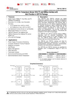
3 JTemperatureAccuracy 25 C to 100 C 2 C(max) 55 C to 125 C 3 C(max)ApplicationsnSystem Thermal ManagementnPersonal ComputersnOffice ElectronicsnElectronic Test EquipmentSimplified Block DiagramI2C is a registered trademark of Philips 2001LM75 Digital Temperature Sensor and Thermal watchdog with Two-Wire interface 2001 National Semiconductor DiagramOrdering InformationOrder NumberPackageMarkingNS PackageNumberSupplyVoltageTransport MediaLM75 CIM-3LM75 CIM-3M08A (SOP-8) (SOP-8) Units on Tape and ReelLM75 CIMM-3T01 CMUA08A (MSOP-8) Units in RailLM75 CIMMX-3T01 CMUA08A (MSOP-8) Units on Tape and ReelLM75 CIM-5LM75 CIM-5M08A (SOP-8)5 VLM75 CIMX-5LM75 CIM-5M08A (SOP-8)5V2500 Units on Tape and ReelLM75 CIMM-5T00 CMUA08A (MSOP-8)5V250 Units in RailLM75 CIMMX-5T00 CMUA08A (MSOP-8)5V3500 Units on Tape and ReelPin DescriptionLabelPin#FunctionTypical ConnectionSDA1I2C Serial Bi-Directional Data Line.
4 Open Controller, tied to a pull-upSCL2I2C Clock InputFrom Shutdown Open Drain OutputPull Up Resistor, Controller Interrupt LineGND4 Power Supply GroundGround+VS8 Positive Supply Voltage InputDC Voltage from 3V to A27,6,5 User-Set I2C Address InputsGround (Low, 0 ) or +VS(High, 1 )SOP-8 and Mini SOP-8DS012658-2DS012658-3 FIGURE 1. Typical Maximum Ratings(Note 1)Supply Voltage to at any Pin to +VS+ Current at any Pin (Note 2)5 mAPackage Input Current (Note 2)20 Output Sink Current10 Output Temperature 65 C to +150 CSoldering Information, Lead TemperatureSOP and MSOP Package (Note 3)Vapor Phase (60 seconds)Infrared (15 seconds)215 C220 CESD Susceptibility (Note 4)Human Body Model1500 VMachine Model100 VOperating RatingsSpecified Temperature RangeTMINto TMAX(Note 5) 55 C to +125 CSupply Voltage Range (+VS)
5 + to + Converter CharacteristicsUnless otherwise noted, these specifications apply for +VS=+5 Vdc for LM75 CIM-5 and LM75 CIMM-5 and +VS=+ Vdc forLM75 CIM-3 and LM75 CIMM-3 (Note 6).Boldface limits apply for TA=TJ=TMINto TMAX;all other limits TA=TJ=+25 C,unless otherwise (Note 12)Limits(Note 7)Units(Limit)AccuracyTA= 25 C to +100 C C (max)TA= 55 C to +125 C Conversion Time(Note 8)100msQuiescent CurrentI2C (max)Shutdown Mode, +VS=3V4 AShutdown Mode, +VS=5V6 Output Saturation VoltageIOUT= (max)(Note 9) Delay(Note 10)1 Conversions (min)6 Conversions (max)TOSD efault Temperature (Note 11)80 CTHYSTD efault Temperature (Note 11)
6 75 CLogic Electrical CharacteristicsDIGITAL DC CHARACTERISTICSU nless otherwise noted, these specifications apply for +VS=+5 Vdc for LM75 CIM-5 and LM75 CIMM-5 and +VS=+ Vdc forLM75 CIM-3 and limits apply for TA=TJ=TMINto TMAX;all other limits TA=TJ=+25 C, unless oth-erwise (Note 12)Limits(Note 7)Units(Limit)VIN(1)Logical 1 Input Voltage+VSx (min)+VS+ (max)VIN(0)Logical 0 Input Voltage (min)+VSx (max)IIN(1)Logical 1 Input CurrentVIN= A (max)IIN(0)Logical 0 Input CurrentVIN= 0V A (max)CINAll Digital Inputs20pFIOHHigh Level Output CurrentVOH=5V100 A (max)VOLLow Level Output VoltageIOL= (max)tOFOutput Fall TimeCL= 400 pF250ns (max)IO= Electrical Characteristics(Continued)
7 I2C Digital SWITCHING CHARACTERISTICSU nless otherwise noted, these specifications apply for+VS=+5 Vdc for LM75 CIM-5 and LM75 CIMM-5 and +VS=+ Vdc forLM75 CIM-3 and LM75 CIMM-3 , CL(load capacitance) on output lines = 80 pF unless otherwise limits ap-ply for TA=TJ=TMINto TMAX;all other limits TA=TJ= +25 C, unless otherwise switching characteristics of the LM75 fully meet or exceed the published specifications of the I2C bus. The following pa-rameters are the timing relationships between SCL and SDA signals related to the LM75. They are not the I2C bus (Note 12)Limits(Note 7)Units(Limit)t1 SCL (Clock) s(min)t2 Data in Set-Up Time to SCL High100ns(min)t3 Data Out Stable after SCL Low0ns(min)t4 SDA Low Set-Up Time to SCL Low (Start Condition)100ns(min)t5 SDA High Hold Time after SCL High (Stop Condition)100ns(min)Note 1:Absolute Maximum Ratings indicate limits beyond which damage to the device may occur.
8 DC and AC electrical specifications do not apply when operatingthe device beyond its rated operating 2:When the input voltage (VI) at any pin exceeds the power supplies (VI<GND or VI>+VS) the current at that pin should be limited to 5 mA. The 20 mAmaximum package input current rating limits the number of pins that can safely exceedthe power supplies with an input current of 5 mA to 3:See AN-450 Surface Mounting Methods and Their Effect on Product Reliability or the section titled Surface Mount found in a current NationalSemiconductor Linear Data Book for other methods of soldering surface mount 4:Human body model, 100 pF discharged through a k resistor.
9 Machine model, 200 pF discharged directly into each 5:LM75 JA( Thermal resistance, junction-to-ambient) when attached to a printed circuit board with 2 oz. foil similar to the one shown inFigure 3is summarizedin the table below:Device NumberNS PackageNumberThermalResistance ( JA)LM75 CIM-3, LM75 CIM-5M08A200 C/WLM75 CIMM-3, LM75 CIMM-5 MUA08A250 C/WNote 6:Both part numbers of the LM75 will operate properly over the +VSsupply voltage range of 3V to The devices are tested and specified for ratedaccuracy at their nominal supply voltage. Accuracy will typically degrade 1 C/V of variation in +VSas it varies from the nominal 7:Limits are guaranteed to National s AOQL (Average Outgoing Quality Level).
10 Note 8:This specification is provided only to indicate how often Temperature data is updated. The LM75 can be read at any time without regard to conversion state(and will yield last conversion result). If a conversion is in process it will be interrupted and restarted after the end of the 9:For best accuracy, minimize output loading. Higher sink currents can affect Sensor accuracy with internal heating. This can cause an error of C at fullrated sink current and saturation voltage based on junction-to-ambient Thermal 10 Delay is user programmable up to 6 over limit conversions before is set to minimize false tripping in noisy 11:Default values set at power 12:Typicals are at TA= 25 C and represent most likely parametric Electrical Characteristics(Continued)DS012658-5 FIGURE 2.