Transcription of Digital Temperature Sensor With I2C Interface …
1 TMP100 EPDIGITAL Temperature Sensor with I2C INTERFACESGLS254B JULY 2005 REVISED OCTOBER 20131 POST OFFICE BOX 655303 DALLAS, TEXAS 75265 DControlled Baseline One Assembly/Test Site, One FabricationSiteDEnhanced Diminishing ManufacturingSources (DMS) SupportDEnhanced Product-Change NotificationDQualification Pedigree DDigital Output: I2C Serial 2-WireDResolution: 9- to 12-Bits, User SelectableDAccuracy: +25C from 255C to +855C (MAX),+35C from 555C to +1255C (MAX) Component qualification in accordance with JEDEC and industrystandards to ensure reliable operation over an extendedtemperature range. This includes, but is not limited to, HighlyAccelerated Stress Test (HAST) or biased 85/85, temperaturecycle, autoclave or unbiased HAST, electromigration, bondintermetallic life, and mold compound life.
2 Such qualificationtesting should not be viewed as justifying use of this componentbeyond specified performance and environmental Quiescent Current: 45 mA, Supply Range: V to VDSmall SOT23-6 PackageapplicationsDPower-Supply Temperature MonitoringDComputer Peripheral Thermal ProtectionDNotebook ComputersDBattery ManagementDThermostat ControlsDEnvironmental MonitoringDElectromechanical Device Temperature description/ordering informationThe TMP100 and TMP101 are 2-wire, serialoutput Temperature sensors available inSOT23 6 packages. Requiring no externalcomponents, the TMP100 and TMP101 arecapable of reading temperatures with a resolutionof TMP100 and TMP101 feature SMBus and I2C Interface compatibility, with the TMP100 allowing up toeight devices on one TMP100 and TMP101 are ideal for extended Temperature measurement in a variety of communication,computer, consumer, environmental, industrial, and instrumentation TMP100M and TMP101M are specified for operation over a Temperature range of 55 C to +125 INFORMATIONTAPACKAGE ORDERABLEPART NUMBERTOP-SIDEMARKING 55 C to 125 CSOT23-6 (DBV)
3 Reel of 3000 TMP100 MDBVREP100E Package drawings, standard packing quantities, thermal data, symbolization, and PCB designguidelines are available at Product PreviewThis integrated circuit can be damaged by ESD. Texas Instruments recommends that all integrated circuits be handled withappropriate precautions. Failure to observe proper handling and installation procedures can cause damage. ESD damage can rangefrom subtle performance degradation to complete device failure. Precision integrated circuits may be more susceptible to damagebecause very small parametric changes could cause the device not to meet its published specifications. These devices have limitedbuilt-in ESD 2004 Texas Instruments IncorporatedPRODUCTION DATA information is current as of publication conform to specifications per the terms of Texas Instrumentsstandard warranty.
4 Production processing does not necessarily includetesting of all be aware that an important notice concerning availability, standard warranty, and use in critical applications ofTexas Instruments semiconductor products and disclaimers thereto appears at the end of this data +DBV PACKAGE(TOP VIEW)TMP100I2C is a registered trademark of Philips EPDIGITAL Temperature Sensor with I2C INTERFACESGLS254B JULY 2005 REVISED OCTOBER 20132 POST OFFICE BOX 655303 DALLAS, TEXAS 75265functional block +4 Temperature1 GNDADD1 maximum ratings over operating free-air Temperature range (unless otherwise noted) Supply voltage, V+ V.. Input voltage range V to V.. Operating free-air Temperature range, TA 55 C to 125 C.
5 Storage Temperature range, Tstg 60 C to 150 C.. Maximum Junction Temperature , TJ 150 C.. Thermal impedance, JA (See Note 1) 165 C/W.. Lead Temperature soldering 300 C.. Stresses beyond those listed under absolute maximum ratings may cause permanent damage to the device. These are stress ratings only, andfunctional operation of the device at these or any other conditions beyond those indicated under recommended operating conditions is notimplied. Exposure to absolute-maximum-rated conditions for extended periods may affect device 1: The thermal impedance, JA, for the DBV package is determined for JEDEC high K PCB (JESD 51 7).
6 Recommended operating conditionsMINNOMMAXUNITS upply voltage, V+ free-air Temperature , TA 55125 Celectrical characteristics over recommended operating free-air Temperature range, VDD = V to V (unless otherwise noted) Temperature inputPARAMETERTEST CONDITIONSMINTYPMAXUNITR ange 55125 CAccuracy ( Temperature error) 25 C to 85 C 2 CAccuracy ( Temperature error) 55 C to 125 C 1 3 CResolutionSelectable CTMP100 EPDIGITAL Temperature Sensor with I2C INTERFACESGLS254B JULY 2005 REVISED OCTOBER 20133 POST OFFICE BOX 655303 DALLAS, TEXAS 75265digital input/outputPARAMETERTEST CONDITIONSMINTYPMAXUNITVIHHigh-level input (V+)(V+) + input voltage (V+)VIINI nput currentVIN = 0 V to 6 V1 AVLow level output voltageIOL = 3 output voltageIOL = 4 to 12bits9-bit4075 Conversion time10-bit80150msConversion time11-bit160300ms12-bit3206009-bit25 Conversion rate10-bit12s/sConversion rate11-bit6s/s12-bit3power supplyPARAMETERTEST CONDITIONSMINTYPMAXUNITS erial bus inactive4575 IQQuiescent currentSerial bus activeSCL = 400 kHz70 AQQS erial bus activeSCL = MHz150 Serial bus currentSerial bus activeSCL = 400 kHz20 ASDS erial bus activeSCL = MHz100 TMP100 EPDIGITAL Temperature Sensor with I2C INTERFACESGLS254B JULY 2005 REVISED OCTOBER 20134 POST OFFICE BOX 655303 DALLAS.
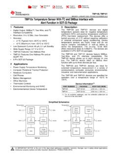
7 TEXAS 75265 APPLICATION INFORMATIONThe TMP100 and TMP101 are Digital Temperature sensors optimal for thermal management and thermalprotection applications. The TMP100 and TMP101 are I2C and SMBus Interface compatible and are specifiedover a Temperature range of 55 C to +125 TMP100 and TMP101 require no external components for operation except for pullup resistors on SCL,SDA, and ALERT although a F bypass capacitor is recommended, as shown in Figure 2: SCL and SDA require pullup resistors for I2C bus (Input) FTMP100 ADD0(Input)356 SCLSDATo I2 CControllerGND24V+1 Figure 1. Typical Connections of the TMP100 The die flag of the lead frame is connected to pin 2. The sensing device of the TMP100 and TMP101 is the chipitself.
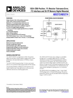
8 Thermal paths run through the package leads as well as the plastic package. The lower thermal resistanceof metal causes the leads to provide the primary thermal path. The GND pin of the TMP100 or TMP101 is directlyconnected to the metal lead frame and is the best choice for thermal maintain the accuracy in applications requiring air or surface Temperature measurement, care should betaken to isolate the package and leads from ambient air Temperature . A thermally conductive adhesive assistsin achieving accurate surface Temperature registerFigure 2 shows the internal register structure of the TMP100 and TMP101. The 8-bit pointer register of theTMP100 and TMP101 is used to address a given data register.
9 The pointer register uses the two LSBs to identifywhich of the data registers should respond to a read or write command. Table 1 identifies the bits of the pointerregister byte. Table 2 describes the pointer address of the registers available in the TMP100 and reset value of P1/P0 is EPDIGITAL Temperature Sensor with I2C INTERFACESGLS254B JULY 2005 REVISED OCTOBER 20135 POST OFFICE BOX 655303 DALLAS, TEXAS 75265I/OControlInterfaceSCLSDAP ointerRegisterTemperatureRegisterConfigu rationRegisterTLOWR egisterTHIGHR egisterFigure 2. Internal Register Structure of TMP100 and TMP101P7P6P5P4P3P2P1P0000000 Register BitsTable 1. Pointer Register ByteP1P0 REGISTER00 Temperature Register (READ Only)01 Configuration Register (READ/WRITE)10 TLOW Register (READ/WRITE)11 THIGH Register (READ/WRITE)Table 2.
10 Pointer Addresses of the TMP100 RegistersTMP100 EPDIGITAL Temperature Sensor with I2C INTERFACESGLS254B JULY 2005 REVISED OCTOBER 20136 POST OFFICE BOX 655303 DALLAS, TEXAS 75265 APPLICATION INFORMATION Temperature registerThe Temperature register of the TMP100 or TMP101 is a 12-bit read-only register that stores the output of themost recent conversion. Two bytes must be read to obtain data and are described in Table 3 and Table 4. Thefirst 12 bits are used to indicate Temperature with all remaining bits equal to zero. Data format for temperatureis summarized in Table 5. Following power-up or reset, the Temperature register reads 0 C until the firstconversion is 3. Byte 1 of the Temperature RegisterD7D6D5D4D3D2D1D0T3T2T1T00000 Table 4.