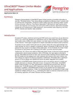
Transcription of LO IF - psemi.com
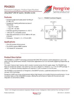
1 2018 pSemi Corp. All rights reserved. Page 1 of 10 Document No. DOC-87599-2 The pe4140 is an ultra-high linearity passive broadband Quad MOSFET array with high dynamic range performance capable of operation beyond GHz. This quad array operates with differential signals at all ports (RF, LO, IF), allowing mixers to be built that use LO powers from -7 dBm to +20 dBm. Typical applications range from frequency up/down-conversion to phase detection for Cellular/PCS Base Stations, Wireless Broadband Communications and STB/Cable modems. The pe4140 is manufactured on peregrine s UltraCMOS process, a patented variation of silicon-on-insulator (SOI) technology on a sapphire substrate, offering the performance of GaAs with the economy and integration of conventional CMOS. product specification Ultra-High Linearity UltraCMOS Broadband Quad MOSFET Array product Description Figure 1. Functional Diagram pe4140 Features Ultimate Quad MOSFET array Ultra-high linearity, broadband performance beyond GHz Ideal for mixer applications Up/down conversion Low conversion loss High LO Isolation Packaged in small 6-lead 3x3 mm DFN Figure 2.
2 Package Type 6-lead DFN RFLOIFS ymbol Characteristics Test Conditions Min Typ Max Units FTYP Operating Frequency Range1 DC GHz VDS Drain-Source Voltage VGS = +3V, IDS = 40 mA 260 320 380 mV VDS Match Drain-Source Voltage Match 12 40 mV VT Threshold Voltage VDS = ; per ASTM F617-00 -100 mV R DS Drain-Source ON Resistance VGS = +3V, IDS = 40 mA Table 1. AC and DC Electrical Specifications @ +25 C Note 1: Typical untested operating frequency range of Quad MOSFET transistors. product specification pe4140 Page 2 of 10 2018 pSemi Corp. All rights reserved. Document No. DOC-87599-2 UltraCMOS RFIC Solutions Table 2. Pin Descriptions Table 3. Absolute Maximum Ratings Electrostatic Discharge (ESD) Precautions This MOSFET device has minimally protected inputs and is highly susceptible to ESD damage. When handling this UltraCMOS device, observe the same precautions that you would use with other ESD-sensitive devices.
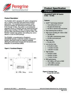
3 Latch-Up Avoidance Unlike conventional CMOS devices, UltraCMOS devices are immune to latch-up. Figure 3. Pin Configuration (Top View) Exceeding absolute maximum ratings may cause permanent damage. Operation should be restricted to the limits in the Operating Ranges table. Operation between operating range maximum and absolute maximum for extended periods may reduce reliability. ExposedSolder Pad(bottom side)IF1RF1RF2IF2LO1LO2456321 Pin No. Pin Name Description 1 IF1 IF Output Connection (Drain) 2 RF1 RF Input Connection (Source) 3 RF2 RF Input Connection (Source) 4 LO2 LO Input Connection (Gate) 5 LO1 LO Input Connection (Gate) 6 IF2 IF Output Connection (Drain) Symbol Parameters/Conditions Min Max Units TST Storage temperature range -65 150 C TOP Operating temperature range -40 85 C VDC + AC Maximum DC plus peak AC voltage across Drain-Source V VDC+AC Maximum DC plus peak AC voltage across Gate-Drain or Gate-Source V VESD HBM1 ESD Voltage 100 V Device Description The pe4140 passive broadband Quad MOSFET array is designed for use in up-conversion and down-conversion applications for high performance systems such as cellular infrastructure equipment and STB/CATV systems.
4 The pe4140 is an ideal mixer core for a wide range of mixer products, including module level solutions that incorporate baluns or other single-ended matching structures enabling three-port operation. The performance level of this passive mixer is made possible by the very high linearity afforded by peregrine s UltraCMOS process. Marking Packaged devices are marked with part number 4140 , date code and lot code. Moisture Sensitivity Level The Moisture Sensitivity Level rating for the pe4140 in the 6-lead 3x3 DFN package is MSL1. Note 1: ML_STD 883 Method product specification pe4140 Page 3 of 10 Document No. DOC-87599-2 2018 pSemi Corp. All rights reserved. Evaluation Kit Figure 4. Evaluation Board Layout Figure 5. Evaluation Board Schematic peregrine specification 101/0090 peregrine specification 102/0115 Applications Support If you have a problem with your evaluation kit or if you have applications questions, please contact applications support: E-Mail: (fastest response) Phone: (858) 731-9400 Note: This is the complete evaluation board schematic; which can be used for multiple configurations.
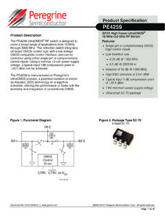
5 Not all components need be populated. Refer to 'typical schematics' on following pages. product specification pe4140 Page 4 of 10 2018 pSemi Corp. All rights reserved. Document No. DOC-87599-2 UltraCMOS RFIC Solutions PE4140165432111222333444555R163 nHT2M/A InputJ4RF InputJ6IF OutFigure 6. Typical Schematic for a PCS Application Table 4. Typical Performance in a PCS Application @ +25 C Parameter Minimum Typical Maximum Units Frequency Range** LO RF IF 1630 1700 -- -- 70 2130 2200 MHz MHz MHz Conversion Loss** (Includes balun losses) dB Isolation** LO-RF LO-IF 36 26 dB dB Input IP3** 32 dBm Input 1 dB Compression** 22 dBm ** Data taken on an Evaluation Board narrow-band tuned to cover the PCS band, IF = 73 MHz low-side, LO drive = 17dBm. product specification pe4140 Page 5 of 10 Document No. DOC-87599-2 2018 pSemi Corp. All rights reserved. -40-35-30-25-20-15-10-501700175018001850 19001950200020502100 Isolation (dB) Frequency (MHz)LO-IF LO-RF 5678910170017501800185019001950200020502 100 Conversion Loss (dB) @ 17dBm LoIF=73 Mhz Low-sideFrequency (MHz)Conversion Loss 0510152025303540170017501800185019001950 200020502100 IIP3 (dBm) @ 17dBm LoFrequency (MHz)Typical Performance Plots in a PCS Application @ +25 C (LO=17 dBm, IF=73 MHz Low-side) Figure 8.
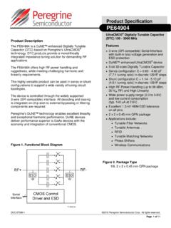
6 Conversion Loss vs. Frequency Figure 9. LO-RF & LO-IF Isolation Figure 7. IIP3 vs. Frequency product specification pe4140 Page 6 of 10 2018 pSemi Corp. All rights reserved. Document No. DOC-87599-2 UltraCMOS RFIC Solutions Figure 10. Typical Schematic for a CATV Application (Reference Designators Refer to locations on Evaluation Board: 101/0090) U1 MLP6-3X3 2 1 3 4 5 6 L2 J3 LO Input 1 T1 1 4 5 3 2 L1 T2 1 4 5 3 2 R16 (Cut short between pads) J4 RF Input 1 T3 ETC1-1-13 1 4 5 3 2 J6 IF Out 1 Note: L1 and L2 provide LO port matching for optimum performance. Typical gate capacitance is approximately pF. Table 5. Typical Performance in a CATV Application @ +25 C Parameter Minimum Typical Maximum Units Frequency Range** LO RF IF 1116 54 -- -- 1062 1926 864 MHz MHz MHz Conversion Loss** (Includes balun losses) dB Isolation** LO-RF LO-IF 40 28 dB dB Input IP3** 23 dBm Input 1 dB Compression** 13 dBm ** Data taken on an Evaluation Board tuned for a broadband CATV application, IF = 1062 MHz, RF drive = -5 dBm, LO drive = 10 dBm.
7 product specification pe4140 Page 7 of 10 Document No. DOC-87599-2 2018 pSemi Corp. All rights reserved. -60-50-40-30-20-100100012001400160018002 000 Isolation (dB)Frequency (MHz)LO-RF LO-IF 024681002004006008001000 Conversion Loss (dB) @10dBm LOFrequency (MHz) 05101520253002004006008001000 IIP3 (dBm) @10dBm LOFrequency (MHz) Typical Performance Plots in a CATV Application @ +25 C Figure 12. Conversion Loss vs. Frequency Figure 13. LO-RF & LO-IF Isolation Figure 11. IIP3 vs. Frequency product specification pe4140 Page 8 of 10 2018 pSemi Corp. All rights reserved. Document No. DOC-87599-2 UltraCMOS RFIC Solutions 6-lead DFN Figure 14. Package Drawing NOTE: The exposed solder pad (on the bottom of the package) is not electrically connected to any other pin (isolated). Figure 15. Marking Specifications 06L SLP (3x3mm) =YY =WW =ZZZZZZ =Pin 1 indicatorLast two digits of assembly yearAssembly work weekAssembly lot code (maximum six characters)4140 YYWWZZZZZZP roduct specification pe4140 Page 9 of 10 Document No.
8 DOC-87599-2 2018 pSemi Corp. All rights reserved. 6-lead DFN Table 7. Ordering Information Order Code Part Marking Description Package Shipping Method 4140-52 4140 PE4140G-06 DFN 3x3mm-3000C Green 6-lead 3x3 mm DFN 3000 units / T&R PE4140B-z 4140 PE4140G-06 DFN 3x3mm-3000C Green 6-lead 3x3 mm DFN 3000 units / T&R 4140-00 pe4140 -EK pe4140 -06 DFN 3x3mm-EK Evaluation Kit 1 / Box EK4140-01 pe4140 -EK pe4140 -06 DFN 3x3mm-EK Evaluation Kit 1 / Box Dimension DFN 3x3 mm Ao Bo Ko P 4 W 8 + , T R7 Quantity 3000 R13 Quantity Note: R7 = 7 inch Lock Reel, R13 = 13 inch Lock Reel Table 6. Dimensions Figure 16. Tape and Reel Specifications Device Orientation in TapeTop ofDevicePin 1 Tape Feed Direction product specification pe4140 Page 10 of 10 2018 pSemi Corp. All rights reserved. Document No. DOC-87599-2 UltraCMOS RFIC Solutions Sales Offices The Americas pSemi Corporation 9380 Carroll Park Drive San Diego, CA 92121 Tel: 858-731-9400 Fax: 858-731-9499 Europe pSemi Europe B timent Maine 13-15 rue des Quatre Vents F-92380 Garches, France Tel: +33-1-4741-9173 Fax : +33-1-4741-9173 For a list of representatives in your area, please refer to our Web site at: High-Reliability and Defense Products Americas San Diego, CA, USA Phone: 858-731-9475 Fax: 848-731-9499 Europe/Asia-Pacific Aix-En-Provence Cedex 3, France Phone: +33-4-4239-3361 Fax: +33-4-4239-7227 pSemi, Asia Pacific (APAC) Shanghai, 200040, China Tel: +86-21-5836-8276 Fax: +86-21-5836-7652 pSemi, Korea #B-2607, Kolon Tripolis, 210 Geumgok-dong, Bundang-gu, Seongnam-si Gyeonggi-do, 463-943 South Korea Tel: +82-31-728-3939 Fax.
9 +82-31-728-3940 pSemi , Japan Teikoku Hotel Tower 10B-6 1-1-1 Uchisaiwai-cho, Chiyoda-ku Tokyo 100-0011 Japan Tel: +81-3-3502-5211 Fax: +81-3-3502-5213 Sales Contact and Information For additional information, contact Sales at Advance Information: The product is in a formative or design stage. The datasheet contains design target specifications for product development. Specifications and features may change in any manner without notice. Preliminary specification : The datasheet contains preliminary data. Additional data may be added at a later date. peregrine reserves the right to change specifications at any time without notice in order to supply the best possible product . product specification : The datasheet contains final data. In the event peregrine decides to change the specifications, peregrine will notify customers of the intended changes by issuing a CNF (Customer Notification Form).
10 The information in this document is believed to be reliable. However, peregrine assumes no liability for the use of this information. Use shall be entirely at the user s own risk.