Transcription of PE29102 - psemi.com
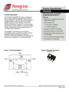
1 PE29102 Document Category: Product SpecificationUltraCMOS High-speed FET Driver, 40 MHz 2017, pSemi Corporation. All rights reserved. Headquarters: 9369 Carroll Park Drive, San Diego, CA, 92121 Product SpecificationDOC-81227-6 (08/2018) High- and low-side FET drivers Dead-time control Fast propagation delay, 9 ns Tri-state enable mode Sub-nanosecond rise and fall time 2A/4A peak source/sink current Package flip chipApplications Class D audio DC DC / AC DC converters Wireless charging Envelope tracking LiDAR Product DescriptionThe PE29102 is an integrated high-speed driver designed to control the gates of external power devices, such as enhancement mode gallium nitride (GaN) FETs.
2 The outputs of the PE29102 are capable of providing switching transition speeds in the sub-nanosecond range for switching applications up to 40 MHz. The PE29102 is optimized for matched dead time and offers best-in-class propagation delay to improve system bandwidth. High switching speeds result in smaller peripheral components and enable innovative designs for applications such as class D audio and wireless charging. The PE29102 is available in a flip chip PE29102 is manufactured on Peregrine s UltraCMOS process, a patented advanced form of silicon-on-insulator (SOI) technology, offering the performance of GaAs with the economy and integration of conventional FET DriverPage 2 of 14 DOC-81227-6 (08/2018) Maximum RatingsExceeding absolute maximum ratings listed in Table 1 may cause permanent damage.
3 Operation should be restricted to the limits in Table 2. Operation between operating range maximum and absolute maximum for extended periods may reduce PrecautionsWhen handling this UltraCMOS device, observe the same precautions as with any other ESD-sensitive devices. Although this device contains circuitry to protect it from damage due to ESD, precautions should be taken to avoid exceeding the rating specified in Table ImmunityUnlike conventional CMOS devices, UltraCMOS devices are immune to 1 PE29102 Functional DiagramTable 1 Absolute Maximum Ratings for PE29102 Parameter/ConditionMinMaxUnitLow-side bias (LSB) to low-side source (LSS) bias (HSB) to high-side source (HSS) signal to LSS 100100 VHSS to GND-1100 VLSS to GND-1100 VESD voltage HBM(*), all pins500 VNote: *Human body model (JEDEC JS 001, Table 2A).
4 DOC-81227-6 (08/2018)Page 3 of FET DriverRecommended Operating ConditionsTable 2 lists the recommended operating conditions for the PE29102 . Devices should not be operated outside the recommended operating conditions listed SpecificationsTable 3 provides the key electrical specifications @ +25 C, VDD = 5V, 100 pF load, HSB and LSB bootstrap diode included unless otherwise 2 Recommended Operating Conditions for PE29102 ParameterMinTypMaxUnitSupply for driver front-end, for high-side driver, for low-side driver, level input voltage, level input voltage, range060 VLSS range060 VOperating temperature 40+105 CJunction temperature 40+125 CTable 3 DC CharacteristicsParameterConditionMinTypM axUnitDC CharacteristicsVDD quiescent currentVDD = quiescent currentVDD = quiescent currentVDD = quiescent currentVDD = quiescent currentVDD = quiescent currentVDD = quiescent currentVDD = quiescent currentVDD = Voltage LockoutUnder voltage release (rising) voltage hysteresis400mVGate DriversHSGPU/LSGPU pull-up HSGPD/LSGPD pull-down HSGPU/LSGPU leakage currentHSB HSGPU = 5V, LSB LSGPU = 5V10 APE29102 High-speed FET DriverPage 4 of 14 DOC-81227-6 (08/2018)
5 LogicTable 4 provides the control logic truth table for the leakage currentHSGPD HSS = 5V, LSGPD LSS = 5V10 ADead-time ControlDead-time control voltages80 k resistor to from HSG going low to LSG going high RDHL = 30 k = k = 150 k = 255 k from LSG going low to HSG going highRDLH = 30 k = k = 150 k = 255 k CharacteristicsLSG turn-off propagation delayAt min dead rise time10 - 90% with 100pF rise time10 - 90% with 100pF fall time90 - 10% with 100pF fall time90 - 10% with 100pF output pulse switching frequency @ 50% duty cycleRDHL = RDLH = 80 k 40 MHzTable 3 DC Characteristics (Cont.)ParameterConditionMinTypMaxUnitTa ble 4 Truth Table for PE29102 ENINHSGPU HSSHSGPD HSSLSGPU LSSLSGPD LSSLLHi ZLHHi ZLHHHi ZHi ZLHLHi ZLHi ZLHHHi ZLHi ZLDOC-81227-6 (08/2018)Page 5 of FET DriverTypical Performance DataFigure 2 through Figure 4 show the typical performance data @ +25 C, VDD = 5V, load = resistor in series with 100 pF capacitor, HSB and LSB bootstrap diode included, unless otherwise 2 Total Quiescent Current (mA)012345678910-4025105 Total Quiescent Current (mA)Temperature ( C)VDD = 4 VVDD = 5 VVDD = 6 VPE29102 High-speed FET DriverPage 6 of 14 DOC-81227-6 (08/2018) 3 UVLO Threshold (V)
6 Figure 4 Dead-time (ns) Threshold (V)UVLO RisingUVLO FallingTemperature ( C)0510152025-4025105 Dead-time (ns) ( C)DOC-81227-6 (08/2018)Page 7 of FET DriverTe s t D i a g r a mFigure 5 shows the test circuit used for obtaining measurements. The two bootstrap diodes shown in the schematic are used for symmetry purposes in characterization. In practice, only the HSB diode is required. Removing the LSB diode will result in higher low-side supply voltage since the diode drop is eliminated. As a result, the dead-time resistor can be adjusted to compensate for any changes in propagation 5 Test Circuit for PE29102 RDHLGNDINHSBVDDHSGPUHSGPDHSSLSBLSSRDLHPH CTLLSGPULSGPDDeadTimeControllerUVLOL evelShifterOutputDriverLogicPhaseControl LevelShifterOutputDriverVDDVINQ1Q2 VSWENPE29102 High-speed FET DriverPage 8 of 14 DOC-81227-6 (08/2018) of OperationGeneralThe PE29102 is intended to drive both the high-side (HS) and the low-side (LS) gates of external power FETs, such as enhancement mode GaN FETs, for power management applications.
7 The PE29102 is suited for applica-tions requiring higher switching speeds due to the reduced parasitic properties of the high resistivity insulating substrate inherent with Peregrine s UltraCMOS driver uses a single-ended pulse width modulation (PWM) input that feeds a dead-time controller, capable of generating a small and accurate dead-time. The dead-time circuit prevents shoot-through current in the output stage. The propagation delay of the dead-time controller must be small to meet the fast switching require-ments when driving GaN FETs. The differential outputs of the dead-time controller are then level-shifted from a low-voltage domain to a high-voltage domain required by the output of the output drivers includes two separate pull-up and pull-down outputs allowing independent control of the turn-on and turn-off gate loop resistance.
8 The low impedance output of the drivers improves external power FETs switching speed and efficiency, and minimizes the effects of the voltage rise time (dv/dt) LockoutAn internal under-voltage lockout (UVLO) feature prevents the PE29102 from powering up before input voltage rises above the UVLO threshold of (typ), and 400 mV (typ) of hysteresis is built in to prevent false triggering of the UVLO circuit. The UVLO must be cleared and the EN pin must be released before the part will be AdjustmentThe PE29102 features a dead-time adjustment that allows the user to control the timing of the LS and HS gates to eliminate any large shoot-through currents, which could dramatically reduce the efficiency of the circuit and potentially damage the GaN FETs.
9 Two external resistors control the timing of outputs in the dead-time controller block. The timing waveforms are illustrated in Figure dead-time resistors only affect the rising edge of the low-side gate (LSG) and high-side gate (HSG) outputs. Dead-time resistor RDLH will delay the rising edge of HSG, thus providing the desired dead-time between LSG falling and HSG rising. Likewise, dead-time resistor RDHL will delay the rising edge of LSG, thus providing the desired dead-time between HSG falling and LSG rising. Figure 7 shows the resulting dead-time versus the external resistor values with both HS and LS bias diode/capacitors installed as indicated in Figure 5.
10 The LS bias diode and capacitor are included for symmetry only and are not required for the part to function. Removing the LS bias diode will increase the LSG voltage by approximately , resulting in a wider separation of the tDHL and tDLH curves in Figure ControlPin 10 (PHCTL) controls the polarity of the gate driver outputs. When PHCTL is low, the HSG will be in phase with the input signal. When PHCTL is high, the LSG will be in phase with the input signal. The PHCTL pin includes an internal pull-down resistor and can be left (08/2018)Page 9 of FET DriverFigure 6 and Figure 7 provide the dead-time description for the 6 Dead-time DescriptionINHSG-HSSLSG-LSStINtDLHtHONtD HLtLONF igure 7 Dead-time between HSG and LSG (ns)0510152025050100150200250300 Dead-time between HSG and LSG (ns)Dead-time Resistance (k )RDLHRDHLPE29102 High-speed FET DriverPage 10 of 14 DOC-81227-6 (08/2018) CircuitFigure 8 shows a class-D audio amplifier application diagram using two PE29102 gate drivers in a full-bridge configuration.