Transcription of Logic-Input CMOS Quad Drivers
1 TC4467/TC4468/TC4469. Logic-Input cmos quad Drivers Features General Description High Peak Output Current: A The TC4467/TC4468/TC4469 devices are a family of Wide Operating Range: four-output cmos buffers/MOSFET Drivers with A. - V to 18 V peak drive capability. Unlike other MOSFET Drivers , these devices have two inputs for each output. The Symmetrical Rise/Fall Times: 25 nsec inputs are configured as logic gates: NAND (TC4467), Short, Equal Delay Times: 75 nsec AND (TC4468) and AND/INV (TC4469). Latch-proof. Will Withstand 500 mA Inductive The TC4467/TC4468/TC4469 Drivers can continuously Kickback source up to 250 mA into ground referenced loads.
2 3 input logic Choices: These devices are ideal for direct driving low current - AND / NAND / AND + Inv motors or driving MOSFETs in a H-bridge configuration ESD Protection on All Pins: 2 kV for higher current motor drive (see Section for details). Having the logic gates onboard the driver can Applications help to reduce component count in many designs. General Purpose cmos logic Buffer The TC4467/TC4468/TC4469 devices are very robust and highly latch-up resistant. They can tolerate up to Driving All Four MOSFETs in an H-Bridge 5 V of noise spiking on the ground line and can handle Direct Small Motor Driver up to A of reverse current on the driver outputs.
3 Relay or Peripheral Drivers The TC4467/4468/4469 devices are available in CCD Driver commercial, industrial and military temperature ranges. Pin-Switching Network Driver Package Types 14-Pin PDIP/CERDIP. 1A 1 14 VDD. 1B 2 13 1Y. 2A 3 TC4467 12 2Y. 2B 4 TC4468 11 3Y. TC4469. 3A 5 10 4Y. 3B 6 9 4B. GND 7 8 4A. 16-Pin SOIC (Wide). 1A 1 16 VDD. 1B 2 15 VDD. 2A 3 14 1Y. TC4467. 2B 4 13 2Y. TC4468. 3A 5 TC4469 12 3Y. 3B 6 11 4Y. GND 7 10 4B. GND 8 9 4A. 2001-2012 Microchip Technology Inc. DS21425C-page 1. TC4467/TC4468/TC4469. logic Diagrams TC4467 TC4468 TC4469 TC446X. VDD VDD VDD. VDD. 14 14 14. 1A 1. 13 1Y 1A 1 13 1Y 1A 1 13 1Y. 1B 2 1B 2 1B 2. 2A 3.
4 12 2Y 2A 3 12 2Y 2A 3 12 2Y Output 2B 4 2B 4 2B 4. 3A 5. 11 3Y 3A 5 11 3Y 3A 5 11 3Y. 3B 6 3B 6 3B 6. 4A 8. 10 4Y 4A 8 10 4Y 4A 8 10 4Y. 4B 9 4B 9 4B 9. 7 7 7. GND GND GND. DS21425C-page 2 2001-2012 Microchip Technology Inc. TC4467/TC4468/TC4469. ELECTRICAL Notice: Stresses above those listed under "Maximum Ratings" may cause permanent damage to the device. This is CHARACTERISTICS a stress rating only and functional operation of the device at those or any other conditions above those indicated in the Absolute Maximum Ratings operation listings of this specification is not implied. Exposure to maximum rating conditions for extended periods may affect Supply Voltage.
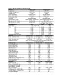
5 +20 V. device reliability. input Voltage .. (GND 5 V) to (VDD + V). Package Power Dissipation: (TA 70 C). mW. CERDIP ..840 mW. SOIC ..760 mW. Package Thermal Resistance: CERDIP R J-A ..100 C/W. CERDIP R J-C ..23 C/W. PDIP R J-A ..80 C/W. PDIP R J-C ..35 C/W. SOIC R J-A ..95 C/W. SOIC R J-C ..28 C/W. Operating Temperature Range: C Version .. 0 C to +70 C. E C to +85 C. M Version ..-55 C to +125 C. Maximum Chip Temperature .. +150 C. Storage Temperature Range ..-65 C to +150 C. ELECTRICAL SPECIFICATIONS. Electrical Characteristics: Unless otherwise noted, TA = +25 C, with V VDD 18 V. Parameters Sym Min Typ Max Units Conditions input logic 1, High input Voltage VIH VDD V Note 3.
6 logic 0, Low input Voltage VIL V Note 3. input Current IIN + A 0 V VIN VDD. Output High Output Voltage VOH VDD V ILOAD = 100 A (Note 1). Low Output Voltage VOL V ILOAD = 10 mA (Note 1). Output Resistance RO 10 15 IOUT = 10 mA, VDD = 18 V. Peak Output Current IPK A. Continuous Output Current IDC 300 mA Single Output 500 Total Package Latch-Up Protection Withstand I 500 mA V VDD 16 V. Reverse Current Switching Time (Note 1). Rise Time tR 15 25 nsec Figure 4-1. Fall Time tF 15 25 nsec Figure 4-1. Delay Time tD1 40 75 nsec Figure 4-1. Delay Time tD2 40 75 nsec Figure 4-1. Power Supply Power Supply Current IS 4 mA. Power Supply Voltage VDD 18 V Note 2.
7 Note 1: Totem pole outputs should not be paralleled because the propagation delay differences from one to the other could cause one driver to drive high a few nanoseconds before another. The resulting current spike, although short, may decrease the life of the device. Switching times are ensured by design. 2: When driving all four outputs simultaneously in the same direction, VDD will be limited to 16 V. This reduces the chance that internal dv/dt will cause high-power dissipation in the device. 3: The input threshold has approximately 50 mV of hysteresis centered at approximately V. input rise times should be kept below 5 sec to avoid high internal peak currents during input transitions.
8 Static input levels should also be maintained above the maximum, or below the minimum, input levels specified in the "Electrical Characteristics" to avoid increased power dissipation in the device. 2001-2012 Microchip Technology Inc. DS21425C-page 3. TC4467/TC4468/TC4469. ELECTRICAL SPECIFICATIONS (OPERATING TEMPERATURES). Electrical Characteristics: Unless otherwise noted, over operating temperature range with V VDD 18 V. Parameters Sym Min Typ Max Units Conditions input logic 1, High input Voltage VIH V Note 3. logic 0, Low input Voltage VIL V Note 3. input Current IIN -10 10 A 0 V VIN VDD. Output High Output Voltage VOH VDD V ILOAD = 100 A (Note 1).
9 Low Output Voltage VOL V ILOAD = 10 mA (Note 1). Output Resistance RO 20 30 IOUT = 10 mA, VDD = 18 V. Peak Output Current IPK A. Continuous Output Current IDC 300 mA Single Output 500 Total Package Latch-Up Protection Withstand I 500 mA V VDD 16 V. Reverse Current Switching Time (Note 1). Rise Time tR 15 50 nsec Figure 4-1. Fall Time tF 15 50 nsec Figure 4-1. Delay Time tD1 40 100 nsec Figure 4-1. Delay Time tD2 40 100 nsec Figure 4-1. Power Supply Power Supply Current IS 8 mA. Power Supply Voltage VDD 18 V Note 2. Note 1: Totem pole outputs should not be paralleled because the propagation delay differences from one to the other could cause one driver to drive high a few nanoseconds before another.
10 The resulting current spike, although short, may decrease the life of the device. Switching times are ensured by design. 2: When driving all four outputs simultaneously in the same direction, VDD will be limited to 16 V. This reduces the chance that internal dv/dt will cause high-power dissipation in the device. 3: The input threshold has approximately 50 mV of hysteresis centered at approximately V. input rise times should be kept below 5 sec to avoid high internal peak currents during input transitions. Static input levels should also be maintained above the maximum, or below the minimum, input levels specified in the "Electrical Characteristics" to avoid increased power dissipation in the device.