Transcription of MCP2200 USB 2.0 to UART Protocol Converter with …
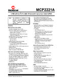
1 2011-2017 Microchip Technology 1 MCP2200 FeaturesUniversal Serial Bus (USB) Supports Full-Speed USB (12 Mb/s) Implements USB Protocol Composite Device: - Communication Device Class (CDC) for Communications and Configuration- Human Interface Device (HID) for I/O control 128-Byte Buffer to Handle Data Throughput at Any uart Baud Rate:- 64-byte transmit- 64-byte receive Fully Configurable VID and PID Assignments and String Descriptors Bus-Powered or Self-Powered USB Compliant: TID 40001150 USB Driver and Software Support Uses Standard Windows Drivers for Virtual Com Port (VCP): Windows XP (SP2 or later), Windows Vista, Windows 7, Windows 8, Windows and Windows 10 Configuration Utility for Initial ConfigurationUniversal Asynchronous Receiver/Transmitter ( uart ) Responds to SET_LINE_CODING Commands to Dynamically Change Baud Rates Supports Baud Rates: 300-1000k Hardware Flow Control uart Signal Polarity OptionGeneral Purpose Input/Output (GPIO) Pins Eight General Purpose I/O pinsEEPROM 256 Bytes of User EEPROMO ther USB Activity LED Outputs (TxLED and RxLED) SSPND Output Pin USBCFG Output Pin (indicates when the enumer-ation is completed) Operating Voltage.
2 Oscillator Input: 12 MHz Electrostatic Discharge (ESD) Protection: >4 kV Human Body Model (HBM) Industrial (I) Operating Temperature: 40 C to +85 CPackage TypesThe device is offered in the following packages: 20-lead VQFN (5x5 mm) 20-lead SOIC 20-lead SSOP2 MCP2200 SOIC, SSOPOSC2 OSC1 RST123420191817 VDDVSSD+D-VusbGP7/TxLED516GP0/SSPNDGP6/R xLED615GP5714GP2GP1/USBCFGMCP22005x5 VQFN*GP6/RxLEDGP5 RSTD-VusbGP3GP0/SSPNDTxRTSRxGP1/USBCFGOS C2 OSC1 VDDVSSGP7/TxLEDEP20119181734151413126789 21131211 CTSRxRTSGP48GP39Tx10D+16GP4GP2511 CTS10* Includes Exposed Thermal Pad (EP); see Ta b l e 1 - to uart Protocol Converter with GPIOMCP2200DS20002228D-page 2 2011-2017 Microchip Technology DiagramUART ControllerUSB Protocol ControllerUSB & Control RegistersOSCR esetControlUSB ClockState ClockGPIOBaud GeneratorVSSVUSBRSTVSSVDDRxTxCTSRTSD+D-O SC1 OSC2 USB LEDsTxLEDRxLEDGP0GP1GP2GP3GP4GP5256 Byte EEPROM 2011-2017 Microchip Technology DESCRIPTIONThe MCP2200 is a USB-to- uart serial Converter thatenables USB connectivity in applications that have aUART interface.
3 The device reduces external compo-nents by integrating the USB termination resistors. TheMCP2200 also has 256 bytes of integrated MCP2200 has eight general purpose input/outputpins. Four pins have alternate functions to indicateUSB and communication status. See Ta b l e 1 - 1 andSection GPIO Module for details about the 1-1:PINOUT DESCRIPTIONPinNameVQFNSSOP,SOICPin TypeStandard FunctionAlternate FunctionGP0/SSPND1316I/OGeneral purpose I/OUSB suspend status pin (refer to Section SSPND Pin Function )GP1/USB-CFG1215I/OGeneral purpose I/OUSB configuration status pin (refer to Section USBCFG Pin Function )GP21114I/OGeneral purpose I/OGP369I/OGeneral purpose I/OGP458I/OGeneral purpose I/OGP547I/OGeneral purpose I/OGP6/RxLED36I/OGeneral purpose I/OUSB receive activity LED output (refer to Section RxLED Pin Function (IN Message) )
4 GP7/TxLED25I/OGeneral purpose I/OUSB transmit activity LED output (refer to Section TxLED Pin Function (OUT Message) )CTS1013 IHardware flow control Clear to Send input signalRTS811 OHardware flow control Request to Send output signalRx912 IUSART RX inputTx710 OUSART TX outputRST14 IReset input must be externally biasedVDD181 PPowerVSS1720 PGroundOSC1192 IOscillator inputOSC2203 OOscillator outputD+1619I/OUSB D+D-1518I/OUSB D-Vusb1417 PUSB power pin (internally connected to ). Should be locally bypassed with a high-quality ceramic Exposed Thermal Pad (EP). Do not electrically 4 2011-2017 Microchip Technology Operating SystemsWindows XP (SP2 and later), Windows Vista, Windows7, Windows 8, Windows and Windows 10 operatingsystems are MCP2200 will enumerate as a USB device afterPower-on Reset (POR).
5 The device enumerates asboth a Human Interface Device (HID) for I/O control,and a Virtual Com Port (VCP). Interface Device (HID)The MCP2200 enumerates as an HID, so the devicecan be configured and the I/O can be controlled. A DLLthat facilitates I/O control through a custom interface issupplied by Com Port (VCP)The VCP enumeration implements the USB-to- uart data ModuleThe control module is the heart of the MCP2200 . Allother modules are tied together and controlled via thecontrol module. The control module manages the datatransfers between the USB and the uart , as well asthe command requests generated by the USB hostcontroller and the commands for controlling thefunction of the uart and INTERFACEThe control module interfaces to the uart and TO THE DEVICEThe MCP2200 can be accessed for reading and writingvia USB host commands.
6 The device cannot beaccessed and controlled via the uart InterfaceThe MCP2200 uart interface consists of the Tx andRx data signals and the RTS/CTS flow control uart is configurable for several baud rates. Theavailable baud rates are listed in Ta b l e 1 - CONFIGURATIONThe default uart configuration is 19200, 8, N, 1. Thedefault start-up baud rate can be changed using theMicrochip-supplied configuration PC , a custom configuration tool can becreated using the Microchip-supplied DLL to set thebaud rate as well as other parameters. See Section Configuration for LINE CODINGThe GET_LINE_CODING and SET_LINE_CODING commands are used to read and set the uart parameters while in operation.
7 For example,HyperTerminal sends the SET_LINE_COMMAND whenconnecting to the port. The MCP2200 responds bysetting the baud rate only. The other parameters (databits, parity, stop bits) remain ErrorsThe primary baud rate setting ( with the rounding errors)is shown in Ta b l e 1 - 3. If baud rates other than the onesshown in the table are used, the error percentage canbe calculated using Equation 1-1 to find the actualbaud 1-3: uart PRIMARY BAUD RATESTABLE 1-2: uart CONFIGURATIONSP arameterConfigurationPrimary Baud RatesSee Table 1-3 Data Bits8 ParityNStop Bits1 Desired RateActual rate% 2011-2017 Microchip Technology 5 MCP2200 EQUATION 1-1:SOLVING FOR ACTUAL BAUD BAUD RATESC ustom baud rates are configured by sending theSET_LINE_CODING USB command, or by using theDLL.
8 See Section Configuration for FLOW CONTROLH ardware flow control uses the RTS and CTS pins asa handshake between two devices. The RTS pin ofone device is typically connected to the CTS of theother is an active-low output that notifies the otherdevice when it is ready to receive data by driving the pinlow. The MCP2200 trip point for deasserting RTS (high)is 63 characters. This is one character short of bufferfull .CTS is an active-low input that notifies the MCP2200when it is ready to send data. The MCP2200 will checkCTS just before loading and sending uart data.
9 If thepin is asserted during a transfer, the transfer willcontinue. Refer to Figure 1-1:RTS/CTS CONNECTIONS Control DisabledThe buffer pointer does not increment (or reset tozero) if the buffer is full. Therefore, if hardware flowcontrol is not enabled and an overflow occurs ( ,65 unprocessed characters received), the new dataoverwrites the last position in the Protocol ControllerThe USB controller in the MCP2200 is full-speed compliant. Composite device (CDC + HID):- CDC: USB-to- uart communications- HID: I/O control, EEPROM access and initial configuration 128-byte buffer to handle data throughput at any uart baud rate:- 64-byte transmit-64-byte receive Fully configurable VID and PID assignments and descriptors (stored on-chip) Bus-powered or configuration, the supplied PC interface storesthe descriptors in the AND RESUMEThe USB Suspend and Resume signals are supportedfor power management of the MCP2200 .
10 The deviceenters Suspend mode when suspend signaling isdetected on the MCP2200 exits Suspend mode when any of thefollowing events occur:1. Resume signaling is detected or USB Reset signal is device reset TransceiverThe MCP2200 has a built-in, full-speed USB internally connected to the USB USB transceiver obtains power from the VUSBpin,which is internally connected to the regulator. Thebest electrical signal quality is obtained when VUSB islocally bypassed with a high-quality ceramic PULL-UP RESISTORSThe MCP2200 devices have built-in pull-up resistorsdesigned to meet the requirements for full-speed POWER OPTIONSThe following are the main power options for theMCP2200: USB Bus-Powered (5V) Self-PoweredActualRate12 MHzint x -------------------=Where.