Transcription of MCP3221 Low-Power 12-Bit A/D Converter with I2C Interface ...
1 2002-2017 Microchip Technology 1 MCP3221 Features 12-Bit Resolution 1 LSB DNL, 2 LSB INL maximum 250 A Max conversion Current 5 nA Typical Standby Current, 1 A maximum I2C Compatible Serial Interface - 100 kHz I2C Standard mode- 400 kHz I2C Fast mode Up to 8 devices on a Single 2-wire Bus ksps in I2C Fast mode Single-Ended Analog Input Channel On-Chip Sample and Hold On-Chip conversion Clock Single-Supply Specified Operation: to Temperature Range:- Extended: -40 C to +125 C Small SOT-23-5 packageApplications Data Logging Multi-Zone Monitoring Handheld Portable Applications Battery-Powered Test Equipment Remote or Isolated Data AcquisitionGeneral DescriptionMicrochip s MCP3221 is a successive approximationA/D Converter (ADC) with a 12-Bit resolution. Availablein the SOT-23 package, this device provides one sin-gle-ended input with very Low-Power on an advanced CMOS technology, theMCP3221 provides a low maximum conversion currentand standby current of 250 A and 1 A, consumption, combined with the smallSOT-23 package, make this device ideal for battery-powered and remote data acquisition to the MCP3221 is performed using a2-wire, I2C compatible Interface .
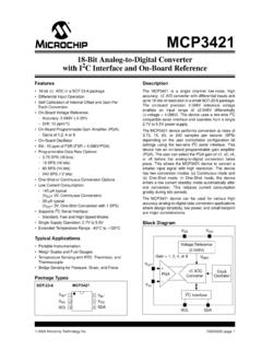
2 Standard (100 kHz)and Fast (400 kHz) I2C modes are available with thedevice. An on-chip conversion clock enablesindependent timing for the I2C and conversion device is also addressable, allowing up to eightdevices on a single 2-wire MCP3221 runs on a single-supply voltage thatoperates over a broad range of to Thisdevice also provides excellent linearity of 1 LSBdifferential nonlinearity (DNL) and 2 LSB integralnonlinearity (INL), Type 5-Pin SOT-23 SCLAINMCP32211235 SDAVSSVDD4 Low-Power 12-Bit A/D Converter with I2C InterfaceMCP3221DS20001732E-page 2 2002-2017 Microchip Technology Block DiagramComparatorSampleand Hold12-bit SARDACI2C InterfaceAINVSSVDDSCLSDAC lockControl Logic + 2002-2017 Microchip Technology CHARACTERISTICSA bsolute Maximum Ratings + input pin VSS .. to VDD + and SCL pins to VDD + Temperature .. -65 C to +150 CAmbient Temperature with power applied.
3 -65 C to +125 CMaximum Junction Temperature .. +150 CESD protection on all pins (HBM) .. 4kV Notice: Stresses above those listed under Absolute Maximum Ratings may cause permanent damage to thedevice. This is a stress rating only and functional operation of the device at those or any other conditions above thoseindicated in the operational listings of this specification is not intended. Exposure to maximum rating conditions forextended periods may affect device ELECTRICAL SPECIFICATIONSE lectrical Characteristics: Unless otherwise noted, all parameters apply at VDD = , VSS = GND, RPU = 2 k TA = -40 C to +85 C, I2C Fast Mode Timing: fSCL = 400 kHz (Note 3). AccuracyResolution 12bitsIntegral NonlinearityINL 2 LSBD ifferential Nonlinearity DNL 1 LSBNo missing codesOffset Error 2 LSBGain Error -1 3 LSBD ynamic PerformanceTotal Harmonic DistortionTHD -82 dBVIN = to @ 1 kHzSignal-to-Noise and DistortionSINAD 72 dBVIN = to @ 1 kHzSpurious Free Dynamic RangeSFDR 86 dBVIN = to @ 1 kHzAnalog InputInput Voltage Range VDD+ VDD Current -1 +1 ASDA/SCL (open-drain output)Data Coding Format Straight Binary High-Level Input VDD VLow-Level Input VoltageVIL VDDVLow-Level Output VoltageVOL = 3 mA, RPU = k Hysteresis of Schmitt Trigger InputsVHYST VfSCL = 400 kHz onlyInput Leakage CurrentILI-1 +1 AVIN = VDD and VDDO utput Leakage CurrentILO-1 +1 AVOUT = VSS and VDDNote 1:Sample time is the time between conversions once the address byte has been sent to the Converter .
4 Refer to Figure :This parameter is periodically sampled and not 100% :RPU = Pull-up resistor on SDA and :SDA and SCL = VSS to VDD at 400 :tACQ and tCONV are dependent on internal oscillator timing. See Figure 5-5 and Figure 5-6 in relation to 4 2002-2017 Microchip Technology SPECIFICATIONSPin Capacitance (all inputs/outputs) CIN, COUT 10pFTA = 25 C, f = 1 MHz; (Note 2)Bus CapacitanceCB 400pFSDA drive low, Power RequirementsOperating CurrentIDD 175250 AStandby CurrentIDDS 1 ASDA, SCL = VDDA ctive Bus CurrentIDDA 120 ANote 4 conversion RateConversion TimetCONV sNote 5 Analog Input Acquisition TimetACQ sNote 5 Sample RatefSAMP fSCL = 400 kHz (Note 1)Electrical Characteristics: Unless otherwise noted, all parameters apply at VDD = , VSS = RangesOperating Temperature RangeTA-40 +125 CExtended Temperature RangeTA-40 +125 CStorage Temperature RangeTA-65 +150 CThermal Package ResistancesThermal Resistance, SOT-23 JA 256 C/WDC ELECTRICAL SPECIFICATIONS (CONTINUED)Electrical Characteristics: Unless otherwise noted, all parameters apply at VDD = , VSS = GND, RPU = 2 k TA = -40 C to +85 C, I2C Fast Mode Timing: fSCL = 400 kHz (Note 3).
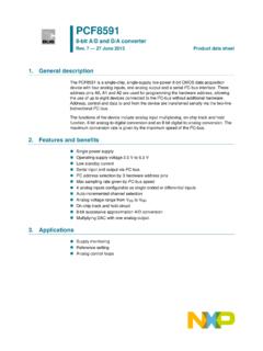
5 1:Sample time is the time between conversions once the address byte has been sent to the Converter . Refer to Figure :This parameter is periodically sampled and not 100% :RPU = Pull-up resistor on SDA and :SDA and SCL = VSS to VDD at 400 :tACQ and tCONV are dependent on internal oscillator timing. See Figure 5-5 and Figure 5-6 in relation to SCL. 2002-2017 Microchip Technology 5 MCP3221 TIMING SPECIFICATIONSFIGURE 1-1:Standard and Fast Mode Bus Timing Characteristics: All parameters apply at VDD = - , VSS = GND, TA = -40 C to +85 Standard ModeClock FrequencyfSCL0 100kHzClock High TimeTHIGH4000 nsClock Low TimeTLOW4700 nsSDA and SCL Rise TimeTR 1000nsFrom VIL to VIH (Note 1)SDA and SCL Fall TimeTF 300nsFrom VIL to VIH (Note 1)Start Condition Hold TimeTHD:STA4000 nsStart Condition Setup TimeTSU:STA4700 nsData Input Setup TimeTSU:DAT250 nsStop Condition Setup TimeTSU:STO4000 nsStop Condition Hold timeTHD:STD4000 nsOutput Valid from Clock TAA 3500nsBus Free Time TBUF4700 nsNote 2 Input Filter Spike SuppressionTSP 50nsSDA and SCL pins (Note 1)I2C Fast ModeClock FrequencyFSCL0 400kHzClock High TimeTHIGH600 nsClock Low TimeTLOW1300 nsSDA and SCL Rise Time TR20 + 300nsFrom VIL to VIH (Note 1)SDA and SCL Fall Time TF20 + 300nsFrom VIL to VIH (Note 1)Start Condition Hold TimeTHD:STA600 nsStart Condition Setup TimeTSU:STA600 nsData Input Hold TimeTHD:DAT0 Input Setup TimeTSU:DAT100 nsStop Condition Setup TimeTSU:STO600 nsStop Condition Hold TimeTHD:STD600 nsOutput Valid from ClockTAA 900nsBus Free TimeTBUF1300 nsNote 2 Input Filter Spike SuppressionTSP 50nsSDA and SCL pins (Note 1)Note 1:This parameter is periodically sampled and not 100% :Time the bus must be free before a new transmission can :STATSPTHD:STATLOWTHD:DATTSU:DATTSU.
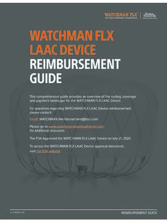
6 STOTBUFTAASCLSDAINSDAOUTMCP3221DS2000173 2E-page 6 2002-2017 Microchip Technology PERFORMANCE CURVESNote: Unless otherwise indicated, VDD = 5V, VSS = 0V, I2C Fast Mode Timing (SCL = 400 kHz), Continuous ConversionMode (fSAMP = ksps), TA = +25 2-1:INL vs. Clock 2-2:INL vs. VDD - I2C Standard Mode (fSCL = 100 kHz).FIGURE 2-3:INL vs. Code (Representative Part).FIGURE 2-4:INL vs. Clock Rate (VDD= ).FIGURE 2-5:INL vs. VDD - I2C Fast Mode (fSCL = 400 kHz).FIGURE 2-6:INL vs. Code (Representative Part, VDD = ).Note:The graphs and tables provided following this note are a statistical summary based on a limited number ofsamples and are provided for informational purposes only. The performance characteristics listed hereinare not tested or guaranteed. In some graphs or tables, the data presented may be outside the specifiedoperating range ( , outside specified power supply range) and therefore outside the warranted Bus Rate (kHz)INL (LSB)Positive INLN egative (V)INL (LSB)Positive INLN egative CodeINL (LSB) Bus Rate (kHz)INL (LSB)Positive INLN egative (V)INL (LSB)Positive INLN egative CodeINL (LSB) 2002-2017 Microchip Technology 7 MCP3221 Note: Unless otherwise indicated, VDD = 5V, VSS = 0V, I2C Fast Mode Timing (SCL = 400 kHz), Continuous ConversionMode (fSAMP = ksps), TA = +25 2-7:INL vs.
7 2-8:DNL vs. Clock 2-9:DNL vs. VDD - I2C Standard Mode (fSCL = 100 kHz).FIGURE 2-10:INL vs. Temperature (VDD= ).FIGURE 2-11:DNL vs. Clock Rate (VDD= ).FIGURE 2-12:DNL vs. VDD - I2C Fast Mode (fSCL = 400 kHz). ( C)INL (LSB)Positive INLN egative Bus Rate (kHz)DNL (LSB)Positive DNLN egative (V)DNL (LSB)Positive DNLN egative ( C)INL (LSB)Negative INLP ositive Bus Rate (kHz)DNL (LSB)Negative DNLP ositive (V)DNL (LSB)Positive DNLN egative DNLMCP3221DS20001732E-page 8 2002-2017 Microchip Technology : Unless otherwise indicated, VDD = 5V, VSS = 0V, I2C Fast Mode Timing (SCL = 400 kHz), Continuous ConversionMode (fSAMP = ksps), TA = +25 2-13:DNL vs. Code (Representative Part).FIGURE 2-14:DNL vs. 2-15:Gain Error vs. 2-16:DNL vs. Code (Representative Part, VDD = ).FIGURE 2-17:DNL vs. Temperature (VDD= ).FIGURE 2-18:Offset Error vs. CodeDNL (LSB) ( C)DNL (LSB)Negative DNLP ositive (V)Gain Error (LSB)Fast Mode(fSCL= 100 kHz)Standard Mode(fSCL= 400 kHz) 1024204830724096 Digital CodeDNL (LSB) ( C)DNL (LSB)Positive DNLN egative (V)Offset Error (LSB)fSCL = 100 kHz & 400 kHz 2002-2017 Microchip Technology 9 MCP3221 Note: Unless otherwise indicated, VDD = 5V, VSS = 0V, I2C Fast Mode Timing (SCL = 400 kHz), Continuous ConversionMode (fSAMP = ksps), TA = +25 2-19:Gain Error vs.
8 2-20:SNR vs. Input 2-21:THD vs. Input 2-22:Offset Error vs. 2-23:SINAD vs. Input 2-24:SINAD vs. Input Signal ( C)Gain Error (LSB)VDD = 5 VVDD = Frequency (kHz)SNR (dB)VDD = 5 VVDD = Frequency (kHz)THD (dB)VDD = = ( C)Offset Error (LSB)VDD = 5 VVDD = Frequency (kHz)SINAD (dB)VDD = 5 VVDD = Signal Level (dB)SINAD (dB)VDD = 5 VVDD = 10 2002-2017 Microchip Technology : Unless otherwise indicated, VDD = 5V, VSS = 0V, I2C Fast Mode Timing (SCL = 400 kHz), Continuous ConversionMode (fSAMP = ksps), TA = +25 2-25:ENOB vs. 2-26:SFDR vs. Input 2-27:Spectrum Using I2C Fast Mode (Representative Part, 1 kHz Input Frequency).FIGURE 2-28:ENOB vs. Input 2-29:Spectrum Using I2C Standard Mode (Representative Part, 1 kHz Input Frequency).FIGURE 2-30:IDD ( conversion ) vs. (V)ENOB (rms)0102030405060708090100110 Input Frequency (kHz)SFDR (dB)VDD = = 5V-130-110-90-70-50-30-10100200040006000 800010000 Frequency (Hz)Amplitude (dB) Frequency (kHz)ENOB (rms)VDD = = 5V-130-110-90-70-50-30-10100500100015002 0002500 Frequency (Hz)Amplitude (dB)fSAMP = (V)IDD ( A) 2002-2017 Microchip Technology 11 MCP3221 Note: Unless otherwise indicated, VDD = 5V, VSS = 0V, I2C Fast Mode Timing (SCL = 400 kHz), Continuous ConversionMode (fSAMP = ksps), TA = +25 2-31:IDD ( conversion ) vs.
9 Clock 2-32:IDD ( conversion ) vs. 2-33:IDDA (Active Bus) vs. 2-34:IDDA (Active Bus) vs. Clock 2-35:IDDA (Active Bus) vs. 2-36:IDDS (Standby) vs. Clock Rate (kHz)IDD ( A)VDD = 5 VVDD = 0 255075100125 Temperature ( C)IDD ( A)VDD = 5 VVDD = (V)IDDA ( A)01020304050607080901000100200300400I2C Clock Rate (kHz)IDDA ( A)VDD = 5 VVDD = 0 255075100125 Temperature ( C)IDDA ( A)VDD = 5 VVDD = (V)IDDS (pA)MCP3221DS20001732E-page 12 2002-2017 Microchip Technology : Unless otherwise indicated, VDD = 5V, VSS = 0V, I2C Fast Mode Timing (SCL = 400 kHz), Continuous ConversionMode (fSAMP = ksps), TA = +25 2-37:IDDS (Standby) vs. 2-38:Analog Input Leakage vs. CircuitsFIGURE 2-39:Typical Test ( C)IDDS (nA) ( C)Analog Input Leakage (nA) FAINMCP3221 VDD = 5 VVCM = FSDASCL2k 2k 2002-2017 Microchip Technology FUNCTIONST able 3-1 lists the function of the 3-1:PIN FUNCTION and VSSThe VDD pin, with respect to VSS, provides power to thedevice as well as a voltage reference for the conversionprocess.
10 Refer to Section Device Power andLayout Considerations for tips on power Input (AIN)AIN is the input pin to the sample and hold circuitry ofthe Successive Approximation Register (SAR) con-verter. Care should be taken in driving this pin. Refer toSection Driving the Analog Input for moreinformation. For proper conversions, the voltage on thispin can vary from VSS to Data (SDA)SDA is a bidirectional pin used to transfer addressesand data into and out of the device. It is an open-drainterminal, therefore, the SDA bus requires a pull-upresistor to VDD (typically 10 k for 100 kHz and 2 k for 400 kHz SCL clock speeds). Refer to Section Connecting to the I2C Bus for more normal data transfer, SDA is allowed to change onlyduring SCL low. Changes during SCL high are reservedfor indicating the Start and Stop conditions. Refer toSection I2C Bus Characteristics for more Clock (SCL)SCL is an input pin used to synchronize the data trans-fer to and from the device on the SDA pin and is anopen-drain terminal.