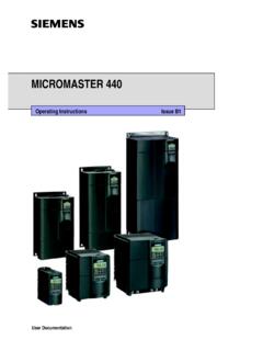
Transcription of MICROMASTER 440 - Siemens
1 MICROMASTER 440. Parameter List Issue B1. User Documentation Getting Started Guide Is for quick commissioning with SDP and BOP. Operating Instructions Gives information about features of the MM440, Installation, Commissioning, Control modes, System Parameter structure, Troubleshooting, Specifications and available options of the MM440. Parameter List The Parameterlist containes the description of all Parameters structured in functional order and a detailed description. The Parameter list also includes a series of function plans. Reference Manual The reference Manual gives elaborate information about engineering communication troubleshooting and maintenance.
2 Catalogues In the catalogue you will find all needs to select a certain inverter, as well as filters chokes, operator panels or communications options. Parameter List 1. Function Diagrams 2. Alarms and 3. Warnings MICROMASTER 440. Parameter List User Documentation Valid for Issue B1. Converter Type MICROMASTER 440. Issue B1. Parameters Issue B1. Warning ! Please refer to all Definitiones and Warnings contained in the Operating Instructions. You will find the Operating Instructions on the Docu CD delivered with your inverter. If the CD is lost, it can be ordered via your local Siemens department under the Order No.
3 6SE6400-5FA00-1AG00. Further information can be obtained from Internet website: Approved Siemens Quality for Software and Training Other functions not described in this document may be is to DIN ISO 9001, Reg. No. 2160-01 available. However, this fact shall not constitute an obligation to supply such functions with a new control, or when The reproduction, transmission or use of this document, or its servicing. contents is not permitted unless authorized in writing. We have checked that the contents of this document Offenders will be liable for damages. All rights including rights correspond to the hardware and software described.
4 There created by patent grant or registration of a utility model or may be discrepancies nevertheless, and no guarantee can be design are reserved. given that they are completely identical. The information contained in this document is reviewed regularly and any Siemens AG 2001. All Rights Reserved. necessary changes will be included in the next edition. We welcome suggestions for improvement. MICROMASTER is a registered trademark of Siemens Siemens handbooks are printed on chlorine-free paper that has been produced from managed sustainable forests. No solvents have been used in the printing or binding process.
5 Document subject to change without prior notice. Order number: 6SE6400-5BB00-0BP0 Siemens -Aktiengesellschaft. Printed in the Federal of Germany MICROMASTER 440 Parameter List 4 6SE6400-5BB00-0BP0. Issue B1 Parameters Parameters MICROMASTER 440. This Parameter List must only be used together with the Operating Instructions or the Reference Manual of the MICROMASTER 440. Please pay special attention to the Warnings, Cautions, Notices and Notes contained in these manuals. Table of Contents 1 7. Introduction to MICROMASTER 440 System Parameters .. 7. Quick commissioning (P0010=1) .. 9. Parameter 11.
6 2 Function Diagrams .. 153. 3 Faults and Alarms .. 161. Fault messages .. 161. Alarm 164. MICROMASTER 440 Parameter List 6SE6400-5BB00-0BP0 5. Parameters Issue B1. MICROMASTER 440 Parameter List 6 6SE6400-5BB00-0BP0. Issue B1 Parameters 1 Parameters Introduction to MICROMASTER 440 System Parameters The layout of the parameter description is as follows. 1 Par number 2 Parameter name 9 Min: 12 Level: [index] 3 CStat: 5 Datatype 7 Unit: 10 Def: 4 P-Group: 6 active: 8 Quick Comm: 11 Max: 2. 13 Description: 1. Parameter number Indicates the relevant parameter number. The numbers used are 4-digit numbers in the range 0000 to 9999.
7 Numbers prefixed with an r indicate that the parameter is a read-only parameter, which displays a particular value but cannot be changed directly by specifying a different value via this parameter number (in such cases, dashes - are entered at the points Unit , Min , Def and Max in the header of the parameter description. All other parameters are prefixed with a P . The values of these parameters can be changed directly in the range indicated by the Min and Max settings in the header. [index] indicates that the parameter is an indexed parameter and specifies the number of indices available.)
8 2. Parameter name Indicates the name of the relevant parameter. Certain parameter names include the following abbreviated prefixes: BI, BO, CI, and CO followed by a colon. These abbreviations have the following meanings: BI = Binector input, parameter selects the source of a binary signal BO = Binector output, parameter connects as a binary signal CI = Connector input, parameter selects the source of an analog signal CO = Connector output, parameter connects as an analog signal CO/BO = Connector/Binector output, parameter connects as an analog signal and/or as a binary signal To make use of BiCo you will need access to the full parameter list.
9 At this level many new parameter settings are possible, including BiCo functionality. BiCo functionality is a different, more flexible way of setting and combining input and output functions. It can be used in most cases in conjunction with the simple, level 2 settings. The BiCo system allows complex functions to be programmed. Boolean and mathematical relationships can be set up between inputs (digital, analog, serial etc.) and outputs (inverter current, frequency, analog output, relays, etc.). 3. CStat Commissioning status of the parameter. Three states are possible: Commissioning C.
10 Ready to run U. Run T. This indicates when the parameter can be changed. One, two or all three states may be specified. If all three states are specified, this means that it is possible to change this parameter setting in all three inverter states MICROMASTER 440 Parameter List 6SE6400-5BB00-0BP0 7. Parameters Issue B1. 4. P-Group Indicates the functional group of the particular. Note Parameter P0004 (parameter filter) acts as a filter and focuses access to parameters according to the functional group selected. 5. Datatype The data types available are shown in the table below. Notation Meaning U16 16-bit unsigned U32 32-bit unsigned I16 16-bit integer I32 32-bit integer Float Floating point 6.