Transcription of Module 10 - NPTEL
1 Module 10. Compression Members Version 2 CE IIT, Kharagpur Lesson 22. Short axially loaded Compression Members Version 2 CE IIT, Kharagpur Instructional Objectives: At the end of this lesson, the student should be able to: state additional assumptions regarding the strengths of concrete and steel for the design of short axially loaded columns , specify the values of design strengths of concrete and steel, derive the governing equation for the design of short and axially loaded tied columns , derive the governing equation for the design of short and axially loaded spiral columns , derive the equation to determine the pitch of helix in spiral columns .
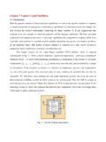
2 Apply the respective equations to design the two types of columns by direct computation, use the charts of SP-16 to design these two types of columns subjected to axial loads as per IS code. Introduction Tied and helically bound are the two types of columns mentioned in of Lesson 21. These two types of columns are taken up in this lesson when they are short and subjected to axially loads. Out of several types of plan forms, only rectangular and square cross-sections are covered in this lesson for the tied columns and circular cross-section for the helically bound columns .
3 axially loaded columns also need to be designed keeping the provision of resisting some moments which normally is the situation in most of the practical columns . This is ensured by checking the minimum eccentricity of loads applied on these columns as stipulated in IS 456. Moreover, the design strengths of concrete and steel are further reduced in the design of such columns . The governing equations of the two types of columns and the equation for determining the pitch of the helix in continuously tied column are derived and explained.
4 The design can be done by employing the derived equation , by direct computation or by using the charts of SP-16. Several numerical examples are solved to explain the design of the two types of columns by direct computation and using the charts of SP-16. Version 2 CE IIT, Kharagpur Further Assumptions Regarding the Strengths of Concrete and Steel All the assumptions required for the derivation of the governing equations are given in of Lesson 21. The stress-strain diagrams of mild steel (Fe 250) and cold worked deformed bars (Fe 415 and Fe 500) are given in and 4, respectively of Lesson 2.
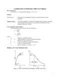
5 The stress block of compressive part of concrete is given in of Lesson 4, which is used in the design of beam by limit state of collapse. The maximum design strength of concrete is shown as constant at fck when the strain ranges from to The maximum design stress of steel is fy. Sections and 12 of Lesson 21 explain that all columns including the short axially loaded columns shall be designed with a minimum eccentricity (cls. and of IS 456). Moreover, the design strengths of concrete and steel are further reduced to fck and fy, respectively, to take care of the minimum eccentricity of times the lateral dimension, as stipulated in of IS 456.
6 It is noticed that there is not attempt at strain compatibility. Also the phenomenon of creep has not been directly considered. ex min greater of (l/500 + D/30) or 20 mm ( ). ey min greater of (l/500 + b/30) or 20 mm The maximum values of lex/D and ley/b should not exceed 12 in a short column as per of IS 456. For a short column, when the unsupported length l =. lex (for the purpose of illustration), we can assume l = 12 D (or 12b when b is considered). Thus, we can write the minimum eccentricity = 12D/500 + D/30 =.
7 , which has been taken as or as the maximum amount of eccentricity of a short column. It is, therefore, necessary to keep provision so that the short columns can resist the accidental moments due to the allowable minimum eccentricity by lowering the design strength of concrete by ten per cent from the value of , used for the design of flexural members. Thus, we have the design strength of concrete in the design of short column as ( )( ) = , say fck. The reduction of the design strength of steel is explained below. For mild steel (Fe 250), the design strength at which the strain is is = However, the design strengths of cold worked deformed bars (Fe 415 and Fe 500) are obtained from of Lesson 2 or of IS 456.
8 Table A of SP-16 presents the stresses and corresponding strains of Fe 415 and Fe 500. Use of Table A of SP-16 is desirable as it avoids error while reading from figures ( or , as mentioned above). From Table A of SP-16, the Version 2 CE IIT, Kharagpur corresponding design strengths are obtained by making linear interpolation. These values of design strengths for which the strain is are as follows: (i) Fe 415: { + ( )/( )} = =. (ii) Fe 500: { + ( )/( )} = =. A further reduction in each of three values is made to take care of the minimum eccentricity as explained for the design strength of concrete.
9 Thus, the acceptable design strength of steel for the three grades after reducing 10 per cent from the above mentioned values are , and for Fe 250, Fe 415 and Fe 500, respectively. Accordingly, cl. of IS 456 stipulates as the design strength for all grades of steel while designing the short columns . Therefore, the assumed design strengths of concrete and steel are and , respectively, for the design of short axially loaded columns . Governing Equation for Short axially loaded Tied columns Factored concentric load applied on short tied columns is resisted by concrete of area Ac and longitudinal steel of areas Asc effectively held by lateral ties at intervals ( of Lesson 21).
10 Assuming the design strengths of concrete and steel are and , respectively, as explained in sec. , we can write Pu = Ac + Asc ( ). where Pu = factored axial load on the member, fck = characteristic compressive strength of the concrete, Ac = area of concrete, fy = characteristic strength of the compression reinforcement, and Asc = area of longitudinal reinforcement for columns . The above equation, given in cl. of IS 456, has two unknowns Ac and Asc to be determined from one equation. The equation is recast in terms of Ag, the gross area of concrete and p, the percentage of compression reinforcement employing Version 2 CE IIT, Kharagpur Asc = pAg/100.