Transcription of Monotonic, Inrush Current Limited Start-Up for …
1 Application Report SLVA156 March 20041 monotonic , Inrush Current Limited Start-Up for Linear Regulators Jeff Falin PMP Portable Products ABSTRACT The output voltage of a linear regulator tends to rise quickly after it is enabled. This often results in a nonmonotonic rise of the output voltage ( , the output voltage overshoots, then dips), which can preclude proper operation of the load circuitry. This application report addresses methods to achieve a monotonic , Inrush Current Limited Start-Up . The simplified block diagram of Figure 1 depicts basic functional blocks of a linear regulator, consisting of a reference, error amplifier, and pass element.
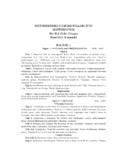
2 Note that undervoltage lockout (UVLO) is not implemented in all linear regulators. Figure 1. Simplified Block Diagram of a Linear Regulator At Start-Up , the error amplifier senses that the output voltage is low and drives the pass element as hard as possible. After a short delay, the pass element pulls a large Inrush Current to charge the output capacitance and/or load abruptly. The delay is caused by three factors: the time required for the input voltage to rise above the UVLO circuitry, if any; the time required for the chip s internal circuitry, particularly the band-gap reference, to power up; and the time required for the regulator to sense its output voltage and turn on the pass element ( , the feedback loop bandwidth).
3 The size of the regulator s output capacitance and the load resistance influences the Start-Up response. If the regulator starts up into a large capacitive or small resistive load, the Inrush Current is large, approaching the regulator s Current limit in some cases. This application report discusses two methods of slew rate limiting a linear regulator s output voltage rise time and, consequently, limiting its Inrush Current at Start-Up , referred to as soft starting the regulator. The TPS796xx, high PSRR, low-noise family of regulators, which are designed for approximately 50- s Start-Up times and thus large Start-Up currents, are used as examples. SLVA156 2 monotonic , Inrush Current Limited Start-Up for Linear Regulators Figures 2 and 3 show the simplest soft- start method in which a FET follows the regulator s output.
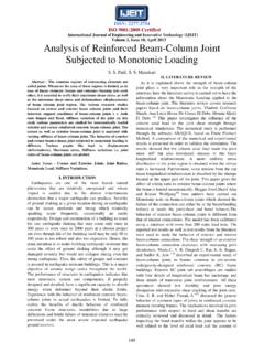
4 The RT and CT determine the ramp time, and CGD provides a smooth, linear ramp of the output voltage. A PMOS FET can be used when trying to soft start voltages that are greater than approximately V, given Current PMOS FET technology. An NMOS FET can be used when trying to soft start any voltage, provided there is a control voltage that is about 1 V larger than the voltage to be soft started, given Current NMOS FET technology. Figure 3 also shows how to provide the control voltage using the TPS3803-01 supply voltage supervisor (SVS) with open-drain output. Figure 2. Soft start Using a PMOS FET Following the Output Note that the soft-starting FET must be placed after the regulator s minimum required output capacitance (COUT) in order to ensure that the regulator remains stable after being enabled.
5 Also, there must be some capacitance, COUT2, after the switch that is at least an order of magnitude larger than CT and CGD. Careful component selection is critical for proper operation of the circuit. First, the PMOS FET must have a nominal threshold voltage (VTH) that is less than the desired output voltage ( , VOUT > VTH) and the NMOS FET must have a threshold voltage that is less than the control voltage (VCNTRL) minus the output voltage (VCNTRL VO (LDO) > VTH). Also, either FET s RDS(on) must be small enough so that the drop across it due to the maximum DC load Current does not significantly reduce the regulated output voltage. CGD is selected to be much larger the FET s inherent gate to drain capacitance (CGD > Crss).
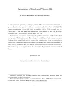
6 For the NMOS FET, the CGD is split, with half going to VO (LDO) and the other half to ground. CGD2 to ground prevents the gate of the FET from charging up when VO (LDO) turns on abruptly. CT is selected to be much larger than the gate to drain capacitance ( , CT >> CGD). RGD is used primarily to prevent a capacitive path from VO_LDO to VOUT and should be between 10 and 100 . RT_PMOS and RT_NMOS are chosen using the following equations: )LDO(OGDSSTH)LDO(OPMOS_TV*Ct*)VV(R (1) )LDO(OGDSSTH)LDO(OCNTRLNMOS_TV*Ct*)VVV(R (2) Where tSS is the desired soft- start time, here 10 ms. These equations are derived in the appendix. SLVA156 monotonic , Inrush Current Limited Start-Up for Linear Regulators 3 Figure 3.
7 Soft- start Using an NMOS FET Following the Output Being Driven by TPS3803-01 SVS Figures 4 and 5 show the rise times of the regulator output voltage with and without the soft- start circuitry for VIN = V and IOUT = 300 mA. The measured rise time is 12 ms, slightly more than the desired 10 ms, but within an acceptable margin considering the variation in Q1 s threshold voltage, VTH. The delay between EN going high and VOUT ramping up is calculated in the appendix as tDELAY. With such a long Start-Up delay, the variation of threshold voltage of Q1, and thus the exact time at which the switch turns on, can be neglected. Figure 4. Results From PMOS FET Soft- start Circuit Following the Output SLVA156 4 monotonic , Inrush Current Limited Start-Up for Linear Regulators Figure 5.
8 Results From NMOS FET Soft- start Circuit Following the Output and TP3803-01 SVS for VCNTRL One disadvantage to this method of soft starting is the difficulty in finding FETs with low enough RDS (on) not to affect regulation under large load currents, or low enough threshold voltages for low output voltages. The Si2333 PMOS FET s RDS(on) is approximately 59 m at VGS = - V; so, at 300-mA output Current , the output voltage could be 18 mV below the nominal voltage, thus increasing the lower tolerance limit of the regulator solution from -3% to -4%. The Si3460 NMOS FET s RDS(on) is less than 30 m at VGS = V V = V; so, at 300-mA output Current , the output voltage could be 9 mV below the nominal voltage, thus increasing the lower tolerance limit of the regulator solution from -3% to The second method, shown in Figure 6, forces a voltage on the feedback pin of the regulator, thereby artificially changing the Start-Up waveform.
9 SLVA156 monotonic , Inrush Current Limited Start-Up for Linear Regulators 5 Figure 6. Soft- start Circuit Using RC and Diode When the enable signal goes high, node VRC charges to VEN. With proper sizing of R1, the feedback node, VFB, artificially rises above the regulated intended feedback voltage of V to VFB2. VFB2 is chosen to be at least 200 mV above the intended feedback voltage but less than a diode drop below VEN. Capacitor CT then discharges through RT and, as the feedback voltage drops, the pass element slowly turns on and the output voltage slowly rises. Diode D2 keeps R1, RT, and CT out of the feedback voltage divider and therefore prevents any degradation in output voltage tolerance or load transient response after Start-Up .
10 Diode D1 clamps node VRC to a diode drop below ground when EN is taken low and is optional. The following equation determines the appropriate size of R1 to raise node VFB to VFB2. = (3) In this example, VFB2 is V + V = V and VINmin is V; so, the calculated value of R1 is 9 k . Once R1 is determined, RT is selected to be much smaller than R1 (roughly a factor of 10 or more, so that it dominates the RC time constant), and then CT can be sized to provide the appropriate rise time. In this example, in order to get a rise time of 5 ms with RT = 499 , CT = 10 F is required. Figure 7 shows the rise time of the regulator with and without the additional circuitry for VIN = V and IOUT = 300 mA.