Transcription of MOUNTING AND HANDLING GUIDELINES FOR …
1 Application Note 101-1. Feb. 2014. MOUNTING AND HANDLING GUIDELINES FOR. TO220/TO220F/TO247 PACKAGES. Introduction The TO220, TO220F and TO247 are the popular packages for power devices because of their versatility and ability to dissipate moderate amounts of heat. This application note describes the basic GUIDELINES for HANDLING power MOSFETs in TO220, TO220 and TO247 packages shown in Figure 1. Please note that only mechanical and soldering GUIDELINES are covered here. Additional precautions are required for isolating high voltage rated devices to meet safety regulations.
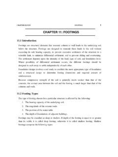
2 (a) TO220. (b)TO220F. Rev. Page 1 of 7. Application Note 101-1. (c)TO247. Figure 1. TO220/TO220F/TO247 General Dimensions(unit:mm). Securing a good thermal interface between the package and heat sink is essential to achieve better heat dissipation and improve the device reliability. Two popular methods of attaching the TO-220 and TO247 devices to a heat sink use either a clip or a small screw with associated hardware. Several types of clip mountings are possible where a clip holds the TO-220 and TO247 deviceS against the heat sink and a screw tightens the clip.
3 A single clip can be designed to hold multiple devices. It is recommended that the clip pressure be applied right on the plastic body of the package for the lowest thermal resistance. (a) MOUNTING through a heat sink (b) MOUNTING on a tapped heat sink Figure 2. MOUNTING with different heat sink Rev. Page 2 of 7. Application Note 101-1. Individual screw MOUNTING methods are shown in Figure 2. Figure 2.(a) shows the hardware sequence when the heat sink is thick and tapped to hold the screw and in Figure 2.
4 (b) screw is held by a nut on the back of the heat sink. The nylon washer isolates the screw from the device tab. The insulator is thermally conductive and transfers the heat away from the device to the heat sink. Even if the device is not required to be isolated from the heat sink, it is necessary to use a filler between the device tab and the heat sink to ensure good thermal contact. This may be a mica or a silicone pad or the old fashioned heat sink compound. Note that in both cases the metallic washer between the screw head and the device tab is rectangular in shape and no spring washers are used on the tab side.
5 If the device is soldered on PCB and attached to the heat sink, make sure that the heat sink attachment is made prior to soldering the leads on PCB. Otherwise the shearing stress between the soldered leads and the tab can easily damage the die during tightening. There is not exposed metal for TO220F with full plastic package so it does not need insulted components and can be fixed by the screw directly. MOUNTING on Heat sink During tightening, the device has a tendency to rotate in the direction of the screw.
6 In order to prevent the rotation, the device is usually restrained sideways, which can subject the die inside to shearing stress as shown in Figure 3 and cause it to delaminate. This may show up as higher Rds in case of power MOSFETs, causing greater heat dissipation and eventual failure. The rectangular washer above the tab is recommended to minimize this stress. Figure 3. Shearing stress on the device Rev. Page 3 of 7. Application Note 101-1. (a) TO220. (b) TO220 F. (c) TO247. Figure 4. Thermal vs torque for AOS TO220/TO220F/TO247.
7 Rev. Page 4 of 7. Application Note 101-1. Table 1. Recommended value of screw size and torque Screw Size Recommended Torque Metric System M3 / ~ N-m Imperial (American) System UNF 6-32 7 ~ 10 in-lb Typical screw sizes are ISO , ISO or 6-32 UNF. Care should be taken not to over-tighten the screw, especially when the operation is done manually. Studies have shown that beyond a certain limit, higher torque on the screw does not improve the thermal resistance any further(Figure 4). Applying higher torques only increases shear stress without any thermal benefits.
8 At excessive torques over 20 in-lb, the screw itself will be stressed, eventually cracking up above 24 in-lb. The following table gives recommended torque ranges with metric and imperial units. A torque controlled screwdriver is strongly recommended for achieving optimum performance. Figure 5. Accoustic scan showing die delamination The pictures above show the damage done to TO220 die as a result of excess torque during MOUNTING . Figure 5. depicts an accoustic scan of three damaged devices. The regions marked in red represent the air bubbles formed due to delamination of the die.
9 Figure 6 on the right is a microscopic view of device #1 which subsequently failed in the application circuit due to excessive heat. Figure 6. Decapped view of device #1. Rev. Page 5 of 7. Application Note 101-1. Lead Bending Though not recommended, bending of leads is acceptable for special applications. Leads may be bent in the same plane or perpendicular to their length as shown in Figure 7. For perpendicular bending, maximal force along the lead axis is lb (20N). Lead bending fixture or a long nose plier is recommended for bending.
10 Minimum distance from bent point to wider section of the lead is inch (2 mm). Figure 7. Lead bending at right angles To avoid damage to the lead and case, follow the correct bending method as shown in Figure 7.(a). The device should be firmly held by a fixture and the lead itself should be held by a fixture or plier while bending the narrow section of the lead. When the leads are bent within the same plane, only narrow section of the leads can be bent. Figure 8 shows an example of plenary bending. Figure 8.