Example: confidence
Phase Shifters - QSL.net
phase shift, dφ, be kept within exceedingly narrow limits for there to be only small variations in frequency, dω, at 180°. The 180° phase shift is commonly designed using switched Low-Pass and High-Pass topology as shown in the figure below: Switched Low …
Tags:
Information
Domain:
Source:
Link to this page:
Documents from same domain
Bias Circuits for RF Devices - QSL.net
www.qsl.netHighly Stable Active Bias for High Frequency Amplifiers The most common form of biasing in RF circuits is the current mirror. This basic stage is used
Impedance Matching - QSL.net
www.qsl.netImpedance Matching Iulian Rosu, YO3DAC / VA3IUL, http://www.qsl.net/va3iul/ The term Impedance is a general term which can be applied to …

Chapter 4 PARABOLIC DISH ANTENNAS - QSL.net
www.qsl.netAperture, Gain, and Efficiency The aperture, gain, and efficiency of an antenna were all defined in Chapter 1 for antennas in general. The aperture A of a dish antenna is the area of the reflector as seen by a

What’s the best antenna? - QSL.net
www.qsl.netWhat’s the best antenna? ... A large beam antenna implies a large tower, rotator, guy cables, concrete, and so forth, and a backyard to put it all in.
CERAMIC FILTER/ CERAMIC DISCRIMINATOR FOR …
www.qsl.net3 This is the PDF file of catalog No.P05E-9. No.P05E9.pdf 00.7.20!MINIMUM ORDER QUANTITY OF CERAMIC FILTER AND DISCRIMINATOR …

Semiconductor IRF512, IRF513
www.qsl.net5-7 irf510, irf511, irf512, irf513 test circuits and waveforms figure 15. unclamped energy test circuit figure 16. unclamped energy waveforms figure 17.
Processing Gain for Direct Sequence Spread TM …
www.qsl.net1 TM AN9633 Processing Gain for Direct Sequence Spread Spectrum Communication Systems and PRISM® Introduction This application note addresses the concept of processing gain (PG) of
Icom IC-746 FAQ - QSL.net
www.qsl.netIC-746 FAQ Recent Changes 2003.02.06 Added another QST article to the article list 2003.02.06 Added current vs voltage chart to power supply section.

Microstrip, Stripline, and CPW Design - QSL.net
www.qsl.netSkin Depth of Planar Conductors At high frequencies, the current flowing in a conductor tends to get confined near the outer surface of the conductor.
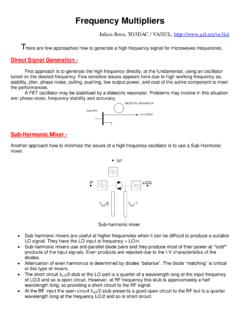
Frequency Multipliers - QSL.net
www.qsl.netUp-Conversion Mixer - The third option to generate a high frequency signal is to use an up converter. The design of an up converter has typically received much less attention in terms of design methodology than down converter
Related documents

Archived Lecture Notes #10 - Phase Equilibria and Phase ...
ocw.mit.eduphase line) is characteristic for materials which have a higher coordination number in the liquid than in the solid phase (H2O, Bi, Si, Ge). Metals, for example have an opposite slope of the solid/liquid phase line, and the liquid phase will condense under pressure to a solid phase. 3.

Unbalanced 3-phase systems Power in 3-phase system
bu.edu.egSince the phase impedances of balanced wye or delta loads contain equal currents, the phase power is one-third of the total power. Phase power Total power For a balanced Δ-connected loads: •The voltage across is phase voltage •The current is line current. •The angle between V & I is the angle on the impedance. Phase power Total power

PHASE 3: PLANNING PHASE
doit.maryland.govphase. Deliverables identified as Updates should be revisited and enhanced as necessary as prescribed in this phase. Deliverables produced during this phase must be reviewed in detail and should follow the approval path as defined in the above table. A signature page or section should accompany each deliverable requiring approval.
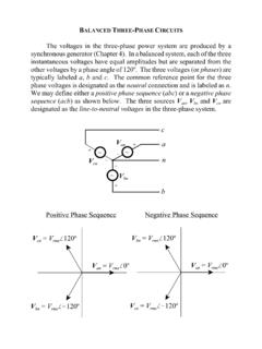
BALANCED THREE-PHASE CIRCUITS
my.ece.msstate.eduphase system by defining the three-phase complex power delivered to the wye load as where Vload and Iline are the load voltage and line current phasors for an individual phase of the three-phase system with a wye-connected load. Inserting the voltage and current phasors into the complex three-phase
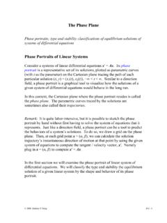
The Phase Plane Phase Portraits of Linear Systems
www.personal.psu.eduthe phase plane. The parametric curves traced by the solutions are sometimes also called their trajectories. Remark: It is quite labor-intensive, but it is possible to sketch the phase portrait by hand without first having to solve the system of equations that it represents. Just like a direction field, a phase portrait can be a tool to predict

Teach Yourself Phase Diagrams and Phase Transformations
www.grantadesign.comA phase diagram (or equilibrium diagram) is a diagram with T and composition as axes, showing the equilibrium constitution. The phase diagram of an alloy made of components A and B, for all combinations of T and X B, defines the A-B system. Binary systems have two components, ternary systems three, and so on. Commercial alloys may

Phase Diagrams and Phase Separation
www.eng.uc.eduimply phase separation. Finally we need to know, if phase separation occurs, how much of each phase is present. Lever Rule for Determining Proportions of Phases Imagine we have a system with 2 phases present (labelled 1 and 2), and two types of atoms A and B. In phase 1 concentration of A = c1 In phase 2 concentration of A = c2

PHASE 5: DESIGN PHASE OBJECTIVE/GOALS
doit.maryland.govDuring the Design Phase, the system is designed to satisfy the requirements identified in the previous phases. The requirements identified in the Requirements Analysis Phase are transformed into a System Design Document that accurately describes the design of the system and that can be used as an input to system development in the next phase.