Transcription of Primary-Side Push-Pull Oscillator with Dead-Time …
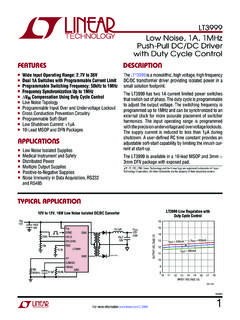
1 UCC28089 SLUS623A -- SEPTEMBER 2004 -- REVISED AUGUST 2006 Primary-Side Push-Pull OSCILLATORWITH Dead-Time Oscillator with ProgrammableDeadtimeDHigh-Current Totem-Pole Dual Output StageDrives Push-Pull Configuration with 1-A Sinkand Source CapabilityDCan be Used in Push-Pull , Half-Bridge, orFull-Bridge TopologiesDOscillator Synchronization OutputDLow Start-Up Current of 130 Run CurrentDOver-Current ShutdownDDigitally Controlled Over-Current/RetryFeatureDUndervoltage Lockout with HysteresisAPPLICATIONSDHigh Efficiency Cascaded ConvertersDInvertersDElectronic BallastsDUninterruptable Power Supplies (UPS)DAC or DC LinksDESCRIPTIONThe UCC28089 is a versatile BiCMOS controller fordc-to-dc or off-line fixed-frequency switching powersupplies.
2 The UCC28089 has dual alternating outputstages in dual-alternating Push-Pull configuration. Bothoutputs switch at half the Oscillator frequency using atoggleflip-flopanddutycycleislimitedtol essthan50%.TYPICAL APPLICATION21437856 UCC28089 SYNCDISCTCSVDDOUTAOUTBGND+--2418 UCC2540 REFSYNCING1151614 VDDPGNDG2--BIASUDG-04112 RARBCTVIN=48 VVO= +Please be aware that an important notice concerning availability, standard warranty, and use in critical applications ofTexas Instrumentssemiconductor products and disclaimers thereto appears at the end of this data DATA information is current as of publication conform to specifications per the terms of Texas Instrumentsstandard warranty.
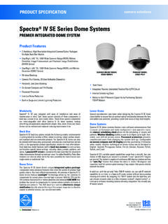
3 Production processing does not necessarily includetesting of all -- SEPTEMBER 2004 -- REVISED AUGUST (CONTINUED)The UCC28089 is optimized for use as the Primary-Side companion controller for a cascaded converter thathassecondary- side control . The device incorporates Dead-Time programming. The synchronization output alsoprovides Dead-Time information. The retry and soft-start duration scales with the Oscillator clock frequency forhigh performance fault UCC28089 also provides primary side under-voltage protection (UVLO), and over-current protection. Boththe soft start and retry after fault durations scale with Oscillator frequency for high performance. The turn-on/offUVLO thresholds are INFORMATIONTEMPERATURE RANGEPACKAGED DEVICES{TEMPERATURERANGETA=TJSOIC--8 (D)-- 4 0 C to 105 CUCC28089D D (SOIC--8) package is available taped and reeled.}
4 Add R suffix to device type ( UCC28089DR) to order quantities of 2,500 devices per reel(for D).CONNECTION DIAGRAM12348765 SYNCDISCTCSVDDOUTAOUTBGNDD PACKAGE (SOIC--8)(TOP VIEW)UCC28089 SLUS623A -- SEPTEMBER 2004 -- REVISED AUGUST MAXIMUM RATINGS over operating free-air temperature (unless otherwise noted) }PARAMETERSYMBOLRATINGUNITSS upply voltage (IDD<10mA)VDD15 VSupply currentIDD20mAOUTA/OUTB sink current (peak)IOUT(sink) source current (peak)IOUT(source)-- 0 . 5 ASYNC sink current (peak)50mASYNC source current (peak)-- 5 0mAAnalog inputs (DIS, CT, CS) + , not to exceed 5 VPower dissipation at TA=25 C (D package)650mWPower dissipation at TA=25 C (DRB package)TBDmWJunction operating temperatureTJ--55 to 150 Storage temperatureTstg--65 to 150oCLead temperature (soldering, 10 sec.)
5 Tsol+300C Stresses beyond those listed under absolute maximum ratings may cause permanent damage to the device. These are stress ratings only, andfunctional operation of the device at these or any other conditions beyond those indicated under recommended operating conditions is notimplied. Exposure to absolute--maximum--rated conditions for extended periods may affect device reliability. All voltages arepositiveinto, thermal limitations and considerations of OPERATION CONDITIONSP arameterSymbolMINTYPMAXUNITSS upply voltage (IDD<10mA) sink current (peak)01025mASYNC source current (peak)-- 2 5-- 1 00mAAnalog inputs (DIS, CT, CS)04 VTiming capacitor rangeCT100100,000pFTiming charge resistor rangeRA32750k Discharge resistor rangeRB0250k Timing charge currentICHG(RA+RB)10300 ASwitching FrequencyfSW1000kHzJunction temperatureTJ-- 4 0105 CUCC28089 SLUS623A -- SEPTEMBER 2004 -- REVISED AUGUST CHARACTERISTICS:TA=--40 C to 105 C for UCC28089, VDD=9V(seeNote1),1 F capacitor from VDD to GND, RA = 110 k , RB = 182 , CT = 220 pF, TA=TJ,(unless otherwise noted).
6 PARAMETERTEST CONDITIONMINTYPMAXUNITSO verall SectionStartup currentVDD < UVLO start threshold (see Note 2)130260 AOperating supply currentCS = 0 V, (see Note 1, Note 2) LockoutStart operating voltage after frequency2 x OUTx frequency, Measured at output(s)180200220kHzCurrent SenseCurrent Shutdown thresholdResetting current to output delayCS from 0 mV to 900 mV45100nsOutputDeadTimeMeasured at OUTA or OUTB90100110nsDead TimeOver temperature80125nsMinimum duty cycleCS = V0%VOL (OUTA or OUTB)IOUT= (OUTA or OUTB)IOUT=--35mA,(VDD VOUT) resistance highTA=25 CIOUT= --1 mA (see Note 4)708090TA= full range IOUT= --1 mA (see Note 4)4080135 Output resistance lowTA=25 CIOUT= 1 mA (see Note 4) TA= full range IOUT= 1 mA (see Note 4) , Rise TimeCLOAD=1nF2850nstf, Fall TimeCLOAD=1nF1330nsSYNCSYNC durationMeasured at SYNC pin7595115tr, delayRising SYNC until falling OUTA or , delayFalling SYNC until rising OUTA or OUTB01450nsSYNC VOHISYNC= --5 mA (VDD VSYNC) VOLISYNC= , Rise TimeCLOAD= 100 pF1530nstf, Fall TimeCLOAD= 100 pF1530nsSoft Start & FaultOUTA/OUTB start delay timeCycles as measured at CT pin575962 OUTA/OUTB soft start durationFirst output stage cycle to first full output stage cycle,CS V457cyclesNOTES: 1.
7 Set VDD above the start threshold before setting at Does not include current of the external Oscillator Ensured by design. Not 100% tested in The pullup / pulldown circuits of the driver are bipolar and MOSFET transistors in parallel. The output resisstance is the RDS(ON)of the MOSFET transistor when the voltage of the driver output isless than the saturation voltage of the bipolar -- SEPTEMBER 2004 -- REVISED AUGUST BLOCK DIAGRAMOUTPUT LOGICUCC280896 OUTB7 OUTA8 VDD4CS2 DIS1 SYNC3CT5 GNDVDDUVLOVDD = VVDDOVERCURRENTCOMPSS VSSCOMPQQSR+ STEPSTARTDELAYRGO7 STEPSOFT--START RAMPREFGOVDD/5 SQQRCKVDD/5 & FAULTOSCILLATORUDG-04101 PIN #NAMEI/OFUNCTION1 SYNCOA ctive when OUTA and OUTB are active, logic LO at all other times such as during under-voltagelock-out and over-current shutdown.
8 When active, SYNC is logic HI (VDD) during the discharge timeof the Oscillator and logic LO (GND) at all other times. The pulse occur during the dead Oscillator timing capacitor discharge pin that allows the dead time to be timing capacitor sense pin. An over current shutdown eventis triggered when the voltage of this pin risesabove pin. Analog and digital signals reference this pin and output drivers return current throughthis pin6 OUTBOD river output, capable of sinking 1 A and A. OUTB signal alternates with output, capable of sinking 1 A and A. OUTA signal alternates with input connection for this -- SEPTEMBER 2004 -- REVISED AUGUST INFORMATIONUCC28089 is an alternating dual-driver output Oscillator with over-current and under-voltage fault performed on the secondary side .
9 This device is especially useful for dc link for topologies such as thecascaded buck converter [1], ac link inverter topologies[2], and inexpensive modified square wave UCC28089 has a brief 5 to 7 cycle leading-edge modulated soft-start cycle so that it will not interfere withsecondary- side controlled soft start. Both systems with off-line self bias and auxiliary bias supplies are morefault tolerant with the UCC28089 because it consistentlyresponds to a fault with a delay of at least 56 oscillatorcycles before Functional DescriptionVDD:Power input connection for this device. Although quiescent VDD current is very low, total supply currentis higher, depending on OUTA and OUTB current and the programmed Oscillator frequency.
10 During faultresponse, the current drops to a lower level because the Oscillator is order to avoid noise problems, position a 1- F ceramic bypass capacitor, connected from VDD to GND, asclose to the chip as possible. The ceramic bypass capacitor is in addition to any energy storage capacitancethat would be used to hold up the VDD voltage during start-up :Ground pin. Analog signals reference this pin and output drivers return current through this pin. For bestresults, use this pin as a local ground point in a star ground and OUTB:Output drivers capable of sinking 1 A and sourcing A. The output pulse alternatesbetween OUTAand addition,a T latch forcestheoutputpulses toalternate inorder toreduce fluxbuildup in a transformer during low duty ratio output is capable of driving the gate of a and DIS: Oscillator timing capacitor pin and timing capacitor discharge pin.