Transcription of AN1175 - Microchip Technology
1 2008 Microchip Technology 1AN1175 INTRODUCTIONT here is a lot of interest in using Brushless DC (BLDC)motors. Among the many advantages to a BLDC motorover a brushed DC motor, we can enumerate thefollowing: The absence of the mechanical commutator allows higher speeds Brush performance limits the transient response in the DC motor With the DC motor you have to add the voltage drop in the brushes among motor losses Brush restrictions on reactance voltage of the armature constrains the length of core reducing the speed response and increasing the inertia for a specific torque The source of heating in the BLDC motor is in the stator, while in the DC motor it is in the rotor, therefore it is easier to dissipate heat in the BLDC Reduced audible and electromagnetic noiseThere are many different types of brushless motors.
2 And the differences are:- The number of phases in the stator- The number of poles in the rotor- The position of the rotor and stator relative to each other (rotor spinning inside the stator vs. rotor spinning outside the stator)This application note will discuss the three-phasemotors. Two-phase motors are discussed in AN1178, Intelligent Fan Control (DS01178) while one-phasemotors are a degenerated form of two-phase a full description of three-phase brushless motors,read the application note Brushless DC Motor ControlMade Easy (DS00857). AN857 is an excellentdescription of brushless motors and how to drive themwith sensor feedback for commutation.
3 With moreadvanced comparator modes and some new softwaretechniques, this application note demonstrates animproved sensorless commutation strategy that has amuch higher CONTROLBLDC motor control consists of two parts. Part 1 iscommutating the motor at the most efficient rate. Part 2is regulating the speed of the motor within definedparameters. The purpose of this application note is toillustrate an elegant sensorless technique that can beimplemented on low-cost microcontrollers. All demon-stration software will operate within an open loop withno speed hardware for a BLDC system can be decomposedinto the following sections:- Motor Power Drivers,- Rotor position detection using back EMF sensing- Current Monitoring- Microcontroller- Microcontroller Power Supply- Speed Set-point InputMotor Power DriverAll BLDC motors require three half-bridge driverstages.
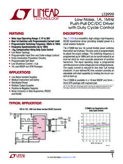
4 Each stage controls one phase of the motor, asillustrated in Table 1 below:Author:Joseph JulicherDieter PeterMicrochip Technology Brushless DC Motor Control with PIC16AN1175DS01175A-page 2 2008 Microchip Technology 1:MOTOR POWER DRIVER Q6 220 VBUSJ2Q3 TPC8405 ToshibaUWVMM8-F1234567834R6220BC847B5/67 /8 WVcc12R2147kMCLRQ7BC847 BOvercurrentDetectionR193k3R2047kC3100nR 7R33201016151476589V_STARV_VW_LV_WV_LU_L RC0/AN4/C2IN+RC1/AN5/C12IN1-RC2/AN6/C12I N2-/P1 DRC3/AN7/C12IN3-/P1 CRC4/C2 OUT/P1 BRC5/CCP1/P1 ARC6/AN8/SSRC7/AN9/SDOPIC16F690RA0/AN0/C 1IN+/ICSPDAT/ULPWURA1/AN1/C12IN0-/VREF/I CSPCLKRA2/AN2/T0 CKI/INT/C1 OUTRA3/MCLR/VPPRA4/AN3/T1G/OSC2/CLKOUTRA 5/T1 CKI/OSC1/CLKINRB4/AN10/SDI/SDARB5/AN11/R X/DTRB6/SCK/SCLRB7/TX/CKU1RA0RA119181743 213121110 VDDC4100nZener ReconstructionBUS-Voltage DividerR13R11R847k47k47k10k10k10kR9R12R1 4V_UV_VUVWV
5 W_HW_LR3220Q5BC847B5/67/8V_LV_HUQ2 TPC8405 Toshiba1243R5220R2220Q1 TPC8405 Toshiba5/67/83421Q4BC847BR10220R1220U_LU _HVDDR4220J3C2C1D1J1100n16V47u16VS3 ADC 2008 Microchip Technology 3AN1175In this sample schematic, there are three P-ChannelMOSFETS controlling the current flow from +VCC intoeach phase. There are also three N-Channel MOS-FETS controlling the current flow from each phase intoground. Between the N-Channel MOSFETS andground there is a small resistor (R7) that allows the cur-rent through the motor to be sensed as a small voltageproportional to the current. Three BJT transistors areused to drive the P channel MOSFETs.
6 The N channelMOSFETs are driven from the PIC MCU I/O pins. Forsmall MOSFETS and/or bipolar transistor outputstages, MOSFET drivers are not required. Back EMF SensingIn order to learn the current position of the rotor, it iscritical that some form of rotor position sensing isincluded. In a sensored design, the rotor position sens-ing is provided by a series of Hall effect sensors thatreact to the permanent magnetics in the rotor. For sen-sorless designs, the rotor position is provided throughknowledge of when a magnetic pole crosses the non-driven phase. During each commutation cycle, onephase is left undriven so it can sense the passing of amagnet on the rotor.
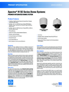
7 The following circuit is self-biasedand uses one comparator to perform the back EMFposition 2:BACK EMF SYSTEMN otice that the back EMF system consists of fourelements with three of them repeating. The purpose ofthese elements is to detect the zero-crossing eventeven when the VDD voltages are changing. There aretwo easy ways to detect the middle of a sine wave. Thefirst method is to make an inverted copy and comparethem. The point where the two waves cross is themidpoint. The second method is to make a reducedamplitude copy and compare them. Again, the pointwhere the two waves cross is the midpoint.
8 Thesimplest method is the second, because it only requiresa single comparator and a few resistors. Because thismotor is a three-phase system, there are six zero-crossings per electrical rotation, the rising edgecrossings and three falling edge crossings. When thecommutation takes place, one of the three phase inputsis selected by writing to the CMxCON0 SFR in themicrocontroller. To save cost, there is not a hardwarefilter on the comparator input, therefore, a noisy motorcan cause false zero-crossings. The solution is asoftware-based majority detector. To simplify thismajority detector, the polarity bit in the CMxCON0register is toggled with each commutation.
9 Toggling thecomparator output polarity with each commutationevent, makes all zero-crossings look like a falling edgeon the comparator MonitoringCurrent monitoring is a nice feature for any motor con-trol, but can be especially nice for BLDC motors. Thebenefits of current monitoring are: High current, No zero-crossings indicate a stuck rotor Over-current limiting Torque controlAdding current monitoring is a simple task of insertinga small sense resistor in the ground return path of thehalf-bridge switching elements. An op amp may benecessary if the sense resistor is very simplest possible over-current monitor is to simplyreset the microcontroller and restart commutation.
10 Thismethod is shown in Figure 1. The current senseresistor is used to drive the base of Q7. This transistorwill cause a Reset of the microcontroller, if externalMCLR is enabled. If external MCLR is not enabled,then the software can be extended to poll this input andtake corrective action if an over current condition software accomplishes the following tasks: Start the motor Detect zero-crossing Commutate the stator Adjust commutation rate to match motor speedStarting the motorStarting the motor is the trickiest part of sensorlessdrives. The simplest method to start the motor is tosimply start commutating at a slow rate and low dutycycle.