Transcription of Programmable DC Electronic Load - Test Equipment Depot
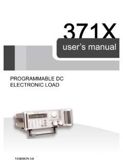
1 Programmable DC Electronic load PEL-2000A Series USER MANUAL GW INSTEK PART NO. 82EL-2004 AEA1 ISO-9001 CERTIFIED MANUFACTURER 99 Washington Street Melrose, MA 02176 Phone 781-665-1400 Toll Free 1-800-517-8431 Visit us at 2016 This manual contains proprietary information, which is protected by copyright. All rights are reserved. No part of this manual may be photocopied, reproduced or translated to another language without prior written consent of the Good Will company. The information in this manual was correct at the time of printing. However, Good Will continues to improve products and reserves the right to change specification, Equipment , and maintenance procedures at any time without of Contents 3 Table of Contents SAFETY INSTRUCTIONS.
2 5 GETTING STARTED .. 10 Main Features .. 12 Series Overview .. 13 Package Contents and 15 Measurement Overview .. 16 Front Panel Overview .. 17 Display Overview Mainframe .. 23 Rear Panel Overview .. 27 Front Panel Overview load Module .. 30 LED Display Overview load Module .. 34 Installation .. 37 load Connections .. 45 Frame Link Connection .. 57 Channel Control Connection .. 59 Go/NoGo Connection .. 62 OPERATING DESCRIPTION .. 63 Operating Mode Description .. 64 Parallel Unit Mode .. 75 Run Program .. 77 Sequence .. 80 OCP Test Automation .. 85 Parallel Dynamic Loading .. 86 Configurations Description .. 87 Interface and File System .. 97 TUTORIALS .. 104 Local loads .. 105 Single Channel load .
3 107 PEL-2000A Series User Manual 4 Parallel load Modules .. 109 Programming .. 111 Sequences .. 113 Frame Link .. 114 Channel Control .. 116 General Configuration Options .. 118 OPERATION .. 119 Local Mode Operation .. 123 Mainframe Basic Operation .. 130 Creating a Program Sequence .. 156 Edit Sequence .. 169 OCP Test Automation .. 179 Channel Configuration .. 186 Mainframe Configuration .. 215 Interface Configuration (settings) .. 230 Save / Recall .. 236 INTERFACE .. 267 Interface Configuration .. 268 FAQ .. 276 APPENDIX .. 277 Fuse Replacement .. 277 Firmware Update .. 278 Calibration .. 279 Range Chart .. 280 Default Settings .. 285 Specifications .. 287 Dimensions .. 298 EC Declaration of Conformity.
4 300 INDEX .. 301 SAFETY INSTRUCTIONS 5 SAFETY INSTRUCTIONSThis chapter contains important safety instructions that you must follow when operating the PEL-2002A/PEL-2004A, and when keeping it in storage. Read the following before operating the PEL-2002A/2004A to ensure your safety and to keep the PEL-2000A series in the best possible condition. Safety Symbols These safety symbols may appear in this manual or on the PEL-2002A/2004A. WARNING Warning: Identifies conditions or practices that could result in injury or loss of life. CAUTION Caution: Identifies conditions or practices that could result in damage to THE PEL-2002A/2004A or to other properties. DANGER High Voltage Attention Refer to the Manual Protective Conductor Terminal Earth (ground) Terminal PEL-2000A Series User Manual 6 Do not dispose Electronic Equipment as unsorted municipal waste.
5 Please use a separate collection facility or contact the supplier from which this instrument was purchased. Safety Guidelines General Guideline CAUTION Do not place any heavy object on the PEL-2002A/2004A. Avoid severe impact or rough handling thatleads to damaging the PEL-2002A/2004A. Do not discharge static electricity to the PEL-2002A/2004A. Do not block or obstruct the cooling fan ventopenings. Do not perform measurement at circuits directlyconnected to Mains (Note below). Do not disassemble the PEL-2002A/2004 Aunless you are qualified as service personnel. The Equipment is not for measurementsperformed for CAT II, III and IV.(Measurement categories) EN 61010-1:2010 specifies the measurement categories and their requirements as follows.
6 The PEL-2002A/2004A falls under category I. Measurement category IV is for measurement performed at the source of low-voltage installation. Measurement category III is for measurement performed in the building installation. Measurement category II is for measurement performed on the circuits directly connected to the low voltage installation. Measurement category I is for measurements performed on circuits not directly connected to INSTRUCTIONS 7 Power Supply WARNING AC Input voltage: 115V/230V switchable,50/60Hz The power supply voltage should not fluctuatemore than 15%. Connect the protective grounding conductor ofthe AC power cord to an earth ground, to avoidelectrical WARNING Fuse type: Make sure the correct type of fuse is installedbefore power up.
7 To avoid fire, only replace the fuse with thespecified type and rating. Disconnect the power cord before fusereplacement. Make sure the cause of a fuse blowout is fixedbefore replacing the the PEL-2000A Disconnect the power cord before cleaning. Use a soft cloth dampened in a solution of milddetergent and water. Do not spray any liquid. Do not use chemicals or cleaners containingharsh material such as benzene, toluene, xylene,and Environment Location: Indoor, no direct sunlight, dust free,almost non-conductive pollution (Note below) Temperature: 0 C to 40 C Altitude: Up to 2000m Transient Overvoltage on the main supply Series User Manual 8 (Pollution Degree) EN 61010-1:2010 specifies the pollution degrees and their requirements as follows.
8 THE PEL-2002A/2004A falls under degree 2. Pollution refers to addition of foreign matter, solid, liquid, or gaseous (ionized gases), that may produce a reduction of dielectric strength or surface resistivity . Pollution degree 1: No pollution or only dry, non-conductivepollution occurs. The pollution has no influence. Pollution degree 2: Normally only non-conductive pollution occurs. Occasionally, however, a temporary conductivity caused by condensation must be expected. Pollution degree 3: Conductive pollution occurs, or dry, non-conductive pollution occurs which becomes conductive due to condensation which is expected. In such conditions, Equipment is normally protected against exposure to direct sunlight, precipitation, and full wind pressure, but neither temperaturenor humidity is environment Location: Indoor Relative Humidity: < 80% Temperature: 10 C to 70 CDisposal Do not dispose this instrument as unsorted municipal waste.
9 Please use a separate collection facility or contact the supplier from which this instrument was purchased. Please make sure discarded electrical waste is properly recycled to reduce environmental impact. SAFETY INSTRUCTIONS 9 Power cord for the United Kingdom When using the PEL-2002A/2004A in the United Kingdom, make sure the power cord meets the following safety instructions. NOTE: This lead/appliance must only be wired by competent persons WARNING: THIS APPLIANCE MUST BE EARTHED IMPORTANT: The wires in this lead are coloured in accordance with the following code: Green/ Yellow: Earth Blue: Neutral Brown: Live (Phase) As the colours of the wires in main leads may not correspond with the coloured marking identified in your plug/appliance, proceed as follows: The wire which is coloured Green & Yellow must be connected to the Earth terminal marked with either the letter E, the earth symbol or coloured Green/Green & Yellow.
10 The wire which is coloured Blue must be connected to the terminal which is marked with the letter N or coloured Blue or Black. The wire which is coloured Brown must be connected to the terminal marked with the letter L or P or coloured Brown or Red. If in doubt, consult the instructions provided with the Equipment or contact the supplier. This cable/appliance should be protected by a suitably rated and approved HBC mains fuse: refer to the rating information on the Equipment and/or user instructions for details. As a guide, a cable of should be protected by a 3A or 5A fuse. Larger conductors would normally require 13A types, depending on the connection method used. Any exposed wiring from a cable, plug or connection that is engaged in a live socket is extremely hazardous.