Transcription of PROGRAMMING WORKBOOK
1 PROGRAMMING WORKBOOKHAAS AUTOMATION, Sturgis , CA 93030 JUNE 1, 2000 JUNE COORDINATE AND INCREMENTAL WITH FUNCTIONS (M CODES)..16 PREPARATORY FUNCTIONS (G CODES)..18 MACHINE OF CANNED ADDRESS POSITION COMMANDS (G00)..28 INTERPOLATION COMMANDS (G01)..29 CIRCULAR INTERPOLATION COMMANDS (G02,G03)..30 INTERPOLATION START-UP ENDING (G04)..42 CIRCULAR POCKET MILLING (G12, G13)..43 CIRCULAR POCKET MILLING PLANE SELECTION (G17, G18, G19)..47 INCH / METRIC SELECTION (G20, G21)..51 REFERENCE POINT DEFINITION AND RETURN (G28)..52 CUTTER COMPENSATION (G40, G41, G42)..53 CUTTER COMPENSATION EXERCISE # COMPENSATION EXERCISE # LENGTH COMPENSATION (G43)..66 WORK COORDINATE SELECTION (G54-59, G110-129, G52, G53, G92).
2 67 NON-MODAL COORDINATE SELECTION (G53)..67 ANOTHER WAY TO SEND MACHINE HOME USING G53 CYCLES - CANNED CYCLE (G80)..70 DRILL - CANNED CYCLE (G81) ..71 SPOT DRILL - CANNED CYCLE (G82)..72 JUNE 2000 PROGRAMMINGCONTENTSDEEP HOLE PECK DRILLING CANNED CYCLE (G83)..73 CANNED CYCLE EXERCISE # - CANNED CYCLE (G84)..78 BORE IN - BORE OUT - CANNED CYCLE (G85)..79 BORE IN - STOP - RAPID OUT - CANNED CYCLE (G86)..80 BORE IN - MANUAL RETRACT - CANNED CYCLE (G87)..81 BORE IN - DWELL - MANUAL RETRACT - CANNED CYCLE (G88)..82 BORE IN - DWELL - BORE OUT - CANNED CYCLE (G89)..83 CANNED CYCLE EXERCISE # SPEED PECK DRILL - CANNED CYCLE (G73)..86 REVERSE TAPPING - CANNED CYCLE (G74)..90 FINE BORING - CANNED CYCLE (G76)..91 BACK BORE - CANNED CANNED CYCLE (G77).
3 92 CANNED CYCLE RETURN PLANES (G98, G99)..93 CANNED CYCLES BOLT HOLE PATTERNS (G70, G71, G72)..94 CANNED CYCLES BOLT HOLE PATTERN (G70)..95 CANNED CYCLES BOLT HOLE PATTERN (G71)..96 CANNED CYCLES BOLT HOLE PATTERN (G72)..97 CANNED CYCLE EXERCISE # (M97, M98, M99)..100 GENERAL PURPOSE POCKET MILLING (G150)..103 FINAL 2000 PROGRAMMINGINTRODUCTIONThis manual provides basic PROGRAMMING principles necessary to begin program-ming the HAAS Milling a CNC (Computerized Numerical Control) machine, the tool is controlled by acomputer and is programmed with a machine code system that enables it to beoperated with minimal supervision and with a great deal of same principles used in operating a manual machine are used in programminga CNC machine.
4 The main difference is that instead of cranking handles to positiona slide to a certain point, the dimension is stored in the memory of the machinecontrol once. The control will then move the machine to these positions each timethe program is order to operate and program a CNC controlled machine, a basic understandingof machining practices and a working knowledge of math is necessary. It is alsoimportant to become familiar with the control console and the placement of the keys,switches, displays, etc., that are pertinent to the operation of the WORKBOOK can be used for both operator s and programmer s. It is intended togive a basic understanding of CNC PROGRAMMING and it s applications. It is notintended as an in-depth study of all ranges of machine use, but as an overview ofcommon and potential situations facing CNC programmers.
5 Much more trainingand information is necessary before attempting to program on the PROGRAMMING manual is meant as a supplementary teaching aid to users of theHAAS Mill. The information in this WORKBOOK may apply in whole or in part to theoperation of other CNC machines. Its use is intended only as an aid in the operationof the HAAS Milling Machine. For a complete explanation and an in-depth descrip-tion, refer to the PROGRAMMING and Operation Manual that is supplied with yourHAAS JUNE 2000 PROGRAMMINGTHE COORDINATE SYSTEMThe first diagram we are concerned with is called a NUMBER LINE. This numberline has a zero reference point that is calledan ABSOLUTE ZERO and may be placed atany point along the number number lineThe number line also has numbered increments on either side of absolutezero.
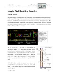
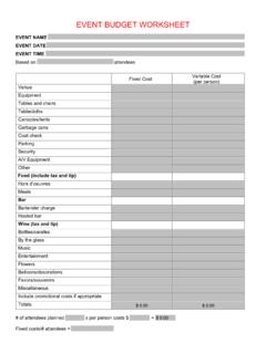
6 Moving away from zero to the right are positive increments. Movingaway from zero to the left are negative increments. The + , or positiveincrements, are understood, therefore no sign is needed. We use positiveand negative signs along with increment value's to indicate its relationshipto zero on the line. If we choose to move to the third increment on the minus(-) side of zero, we would call for -3. If we choose the second increment inthe plus range, we would call for 2. Our concern is the distance and thedirection from that zero may be placed at any point along the line, and thatonce placed, one side of zero has negative increments and the other sidehas positive machine illustration shows threedirections of travel available on a ver-tical machine center.
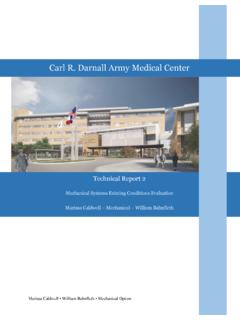
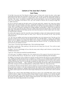
7 To carry the num-ber line idea a little further, imaginesuch a line placed along each axis ofthe machine. It shows the three direc-tions to position the coordinatesaround a part origin, which is wherethese number lines intersect on a ver-tical machining center with the X, Y,and Z axis first number line is easy to con-ceive as belonging to the left-to-right,or X , axis of the machine. If weplace a similar number line along thefront-to-back, or Y axis, the incre-ments (not the table) toward the op-erator, from Y zero, are the negativeincrements. The increments on theother side of zero away from the op-erator are positive number line3 JUNE 2000 PROGRAMMINGvThe third axis of travel on our machine is the up-and-down, or Z axis. When weplace a number line on the Z travel, the positive increments are up above zero, andthe negative values are down below zero.
8 The increments of each number line onHAAS machining centers equals .0001 inches. Also, while a line theoreticallytravels infinitely in either direction once established, the three lines placed alongthe X, Y, and Z axes of the machine do not have unlimited accessibility. That is tosay, we are limited by the range of travel on the model of machining X-axis travel Y-axis travel Z-axis travelVF-E / VF-0 / VF120"16"20"VF-EXT / VF-OE30"16"20"VF230"16"20"VF340"20"25"VF 450"20"25"VF550"25"25"VF664"32"30"VF784" 32"30"VF864"40"30"VF984"40"30"VF10120"32 "30"VF11120"40"30"VR11120"40"30"HS-1/1R/ 1RP24"20"22"HS-2RP38"35"30"Remember, when we are moving the machine, we are concerned with positioningthe center of the spindle in relation to X,Y and Z zero.
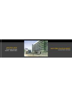
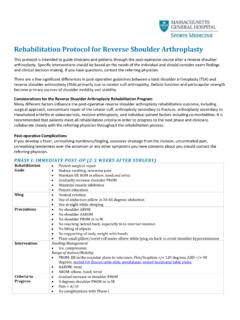
9 Although the machine tableis the moving part, we have to keep in mind our coordinates are based off ourtheoretical spindle in mind that the part zero position may be defined at any point along each ofthe three axes, and will usually be different for each setup of the is noteworthy to mention here that the Z-axis is set with the machine zero positionin the upward position, or the tool change position. This will place most all Z movesin a negative range of JUNE 2000 PROGRAMMINGFig. 1-4 view shows the X,Y work zero grid from above. The work part zero for theZ-axis is usually set at the top of the part surface, and this will be entered in the toollength offset as a negative value for each tool. The range of Z-axis travel on theHAAS VF-1, for example, is 20 inches total; four of these inches are above toolchange position and is listed as a positive tool length offset, and 16 inches arebelow tool change position and listed as a negative.
10 The diagram shows a top viewof the grid as it would appear on the machine tool. This view shows the X and Y axesas the operator faces a vertical machine table. Note that at the intersection of thetwo lines, a common zero point is established. Thefour areas on each side and above and below thelines are called QUADRANTS and make up thebasis for what is known as rectangular 1 IS ON THE TOP RIGHT = X+ Y+QUADRANT 2 IS ON THE TOP LEFT = X- Y+QUADRANT 3 IS ON THE BOTTOM LEFT = X- Y-QUADRANT 4 IS ON THE BOTTOM RIGHT = X+ Y-Whenever we set a zero point somewhere on the X-axis and, a zero point somewhere on the Y-axis, wehave automatically set a work zero point and anintersection of the two number lines. This intersec-tion where the two zeros come together will auto-matically have the four quadrants to its sides, above,and below it.