Transcription of Pulse Width Modulation (PWM) Tutorial
1 Pulse Width Modulation (PWM) Tutorial Copyright 2005 by Datadog SystemsPulse Width Modulation using digital pulses to create some analog value other than just high and low signal levels. Manydigital systems are powered by a 5-Volt power supply, so if you filter a signal that has a 50% duty cycle you get an averagevoltage of Volts. Other duty cycles produce any voltage in the range of 0 to 100% of the high voltage, depending upon thePWM duty cycle is defined as the percentage of digital high to digital low signals present during a PWM PWM resolution is defined as the maximum number of pulses that you can pack into a PWM PWM period is an arbitrarily time period in which PWM takes place.
2 It is chosen to give best results for your particular for PWM: 1) To digitally create an analog output voltage level for control functions and power supplies. 2) To digitally create analog signals for arbitrary waveforms, sounds, music and PWM to generate an analog voltage level: A common use is in power supplies. The PWM resolution is selected to beequal to or greater than the resolution requirements of the power supply. A 5-Volt power supply that can be adjusted to +/- 1 milli-Volt should use a PWM resolution of 5,000 or greater.
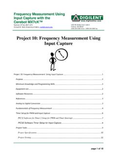
3 The PWM output is then filtered to obtain acceptable ripple. The filter canbe a simple low-pass above figure shows a PIC microcontroller generating a 50% duty cycle PWM signal at 5,000 Hz, a two-section 5,000 Hz low-pass filter and a pass-transistor with a direct current input of + Volts. The filter frequency = 1/2 pi RC for each PWM to generate an analog waveform: Any shape waveform can be generated by outputting a sequence of PWMvalues that correspond to multiple points on the waveform. When you use more points, heavier filtering and greater PWMresolution, you can represent fast waveforms with great accuracy.
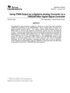
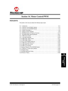
4 In practice, a PIC microcontroller can easily output reasonablydecent sine waveforms in the voice frequency range. The 4 KHz sine waveform below uses a 16 level resolution PWM signal and16 points on the sine wave. The PWM frequency is about 30 KHz using an on/off cycle, and about 500 KHz using a distributed cycle. The distributed cycle produces smoother results, as shown on/off PWM duty cycle: Starts with eight pulses high for the first part of the PWM cycle, then finishes with eight low pulses for the remainder of the PWM cycle.
5 The ratio of the percent high time to the percent low time is called the duty that the PWM frequency of the on/off PWM for any duty cycle in the drawing above is: F = 1/P = 1 / 16us = distributed PWM cycle: Also uses eight high pulses and eight low pulses as does the previous example, but spreadsthem out during the entire PWM cycle. Note that the PWM frequency of the distributed PWM 50% duty cycle in the drawingabove is: F = 1/P = 1 / 2us = 500 KHz. This is great if most of your PWM is around 50% duty cycle but the PWM frequencygradually slows to as you approach 0% or 100%.
6 Why the PWM frequency is important: The PWM is a large amplitude digital signal that swings from one voltage extreme to theother. And, this wide voltage swing takes a lot of filtering to smooth out. When the PWM frequency is close to the frequency ofthe waveform that you are generating, then any PWM filter will also smooth out your generated waveform and drastically reduceits amplitude. So, a good rule of thumb is to keep the PWM frequency much higher than the frequency of any waveform yougenerate. Finally, filtering pulses is not just about the Pulse frequency but about the duty cycle and how much energy is in thepulse.
7 The same filter will do better on a low or high duty cycle Pulse compared to a 50% duty cycle Pulse . Because the widerpulse has more time to integrate to a stable filter voltage and the smaller Pulse has less time to disturb : PWM is the poor mans digital -to- analog converter (DAC). It has problems not shared by other DACs, such asspeed and instantaneous voltage output, but it is the least expensive way to get an analog voltage output from a other uses are to operate relays and solenoids that require high pull-in current and more moderate hold current.
8 Or fordevices that require a lower operating voltage than your microcontroller, such as a lamp. There are additional ways toimprove PWM, such as using LC filters. Although they cost more, they will not drop the voltage as do RC filters. Also, you canuse two microcontroller I/O pins to mix on/off PWM with distributed PWM to obtain twice the resolution. These and othermethods are discussed in the Datadog Systems PIC10F2XX tutorials. I hope this PWM Tutorial was useful to regards,John Massa