Transcription of 16-Bit Microcontrollers and Digital Signal …
1 2009-2012 Microchip Technology 1dsPIC33 EPXXX(GP/MC/MU)806/810/814and PIC24 EPXXX(GP/GU)810/814 Operating Conditions to , -40 C to +125 C, DC to 60 MIPS to , -40 C to +85 C, DC to 70 MIPSCore: 16-Bit dsPIC33E/PIC24E CPU Code-Efficient (C and Assembly) architecture Two 40-Bit Wide Accumulators Single-Cycle (MAC/MPY) with Dual Data Fetch Single-Cycle Mixed-Sign MUL Plus Hardware Divide 32-Bit Multiply SupportClock Management 2% Internal Oscillator Programmable PLLs and Oscillator Clock Sources Fail-Safe Clock Monitor (FSCM) Independent Watchdog Timer Fast Wake-up and Start-upPower Management Low-Power Management modes (Sleep, Idle, Doze) Integrated Power-on Reset and Brown-out Reset mA/MHz Dynamic Current (typical) 60 A IPD Current (typical)High-Speed PWM Up to Seven PWM Pairs with Independent Timing Dead Time for Rising and Falling Edges ns PWM Resolution PWM Support for.
2 - DC/DC, AC/DC, Inverters, PFC, Lighting- BLDC, PMSM, ACIM, SRM Programmable Fault Inputs Flexible Trigger Configurations for ADC ConversionsAdvanced Analog Features Two Independent ADC modules:- One ADC configurable as 10-bit, Msps with four S&H or 12-bit, 500 ksps with one S&H- One 10-bit ADC, Msps with four S&H- Eight S&H using both ADC 10-bit modules- 24 analog channels (64-pin devices) up to 32 analog channels (100/121/144-pin devices) Flexible and Independent ADC Trigger Sources Comparators:- Up to three Analog Comparator modules- Programmable references with 32 voltage points Timers/Output Compare/Input Capture 27 General Purpose Timers:- Nine 16-Bit and up to four 32-bit Timers/Counters- 16 OC modules configurable as Timers/Counters- Two 32-bit Quadrature Encoder Interface (QEI) modules configurable as Timers/Counters 16 IC modules Peripheral Pin Select (PPS) to allow Function Remap Real-Time Clock and Calendar (RTCC) moduleCommunication Interfaces USB OTG-Compliant Full-Speed Interface Four UART modules (15 Mbps)- Supports LIN/J2602 protocols and IrDA Four 4-Wire SPI modules (15 Mbps) Two ECAN modules (1 Mbaud) CAN Support Two I2C modules (up to 1 Mbaud) with SMBus Support Data Converter Interface (DCI) module with Support for I2S and Audio Codecs PPS to allow Function Remap Parallel Master Port (PMP) Programmable Cyclic Redundancy Check (CRC)Direct Memory Access (DMA)
3 15-Channel DMA with User-Selectable Priority Arbitration UART, USB, SPI, ADC, ECAN , IC, OC, Timers, DCI/I2S, PMPI nput/Output Sink/Source 10 mA on All Pins 5V Tolerant Pins Selectable Open-Drain, Pull-ups and Pull-Downs Up to 5 mA Overvoltage Clamp Current External Interrupts on All I/O pinsQualification and Class B Support AEC-Q100 REVG (Grade 1 -40 C to +125 C) Planned AEC-Q100 REVG (Grade 0 -40 C to +150 C) Planned Class B Safety Library, IEC 60730 Debugger Development Support In-Circuit and In-Application Programming Five Program and Three Complex Data Breakpoints IEEE Compatible (JTAG) Boundary Scan Trace and Run-Time Watch16-Bit Microcontrollers and Digital Signal Controllers with High-Speed PWM, USB and Advanced AnalogdsPIC33 EPXXX(GP/MC/MU)806/810/814 and PIC24 EPXXX(GP/GU)810/814DS70616G-page 2 2009-2012 Microchip Technology (GP/MC/MU)806/810/814 and PIC24 EPXXX(GP/GU)810/814 PRODUCT FAMILIESThe device names, pin counts, memory sizes andperipheral availability of each device are listed inTable 1.
4 Their pinout diagrams appear on the 1:dsPIC33 EPXXX(GP/MC/MU)806/810/814 and PIC24 EPXXX(GP/GU)810/814 CONTROLLER FAMILIESD evicePinsPackagesProgram Flash Memory (Kbyte)(1)RAM (Kbyte)(2)Remappable PeripheralsRTCCI2C CRC Generator10-Bit/12-Bit ADC(8)USBI/O Pins16-Bit Timer(3,4) Input CaptureOutput Compare (with PWM)Motor Control PWM(Channels)(5)QEIUART with IrDA SPIECAN External Interrupts(6)DMA Controller (Channels)DCIA nalog Comparators/Inputs Per Comparator(7) Parallel Master PortdsPIC33EP256MU80664 QFN, TQFP28028916168244251513/41212 ADC,24 ch1Y51dsPIC33EP256MU810100 TQFP280289161612244251513/41212 ADC,32 ch1Y83121 TFBGAdsPIC33EP256MU814 144 TQFP, LQFP280289161614244251513/41212 ADC,32 ch1Y122dsPIC33EP512GP80664 QFN, TQFP5365291616 44251513/41212 ADC,24 ch Y53dsPIC33EP512MC80664 QFN, TQFP53652916168244251513/41212 ADC,24 ch Y53dsPIC33EP512MU810100 TQFP536529161612244251513/41212 ADC,32 ch1Y83121 TFBGAdsPIC33EP512MU814 144 TQFP, LQFP536529161614244251513/41212 ADC,32 ch1Y122 PIC24EP256GU810100 TQFP28028916160044251513/41212 ADC,32 ch1Y83121 TFBGAPIC24EP256GU814144 TQFP, LQFP28028916160044251513/41212 ADC,32 ch1Y122 PIC24EP512GP80664 QFN, TQFP5865291616 44251513/41212 ADC,24 ch Y53 PIC24EP512GU810100 TQFP53652916160044251513/41212 ADC.
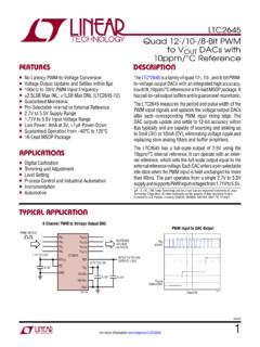
5 32 ch1Y83121 TFBGAPIC24EP512GU814144 TQFP,LQFP53652916160044251513/41212 ADC,32 ch1Y122 Note1:Flash size is inclusive of 24 Kbytes of auxiliary Flash. Auxiliary Flash supports simultaneous code execution and self-erase/programming. Refer to Section 5. Flash Programming (DS70609) in the dsPIC33E/PIC24E Family Reference Manual .2:RAM size is inclusive of 4 Kbytes of DMA RAM (DPSRAM) for all :Up to eight of these timers can be combined into four 32-bit :Eight out of nine timers are :PWM Faults and Sync signals are :Four out of five interrupts are :Comparator output is :The ADC2 module supports 10-bit mode only. 2009-2012 Microchip Technology 3dsPIC33 EPXXX(GP/MC/MU)806/810/814 and PIC24 EPXXX(GP/GU)810/814 Pin Diagrams64-Pin QFNNote 1:The RPn/RPIn pins can be used by any remappable peripheral with some limitation.
6 SeeSection Peripheral Pin Select for available peripherals and for information on :Every I/O port pin (RAx-RGx) can be used as change notification (CNAx-CNGx). See Section I/O Ports for more :The availability of I2C interfaces varies by device. Selection (SDAx/SCLx or ASDAx/ASCLx) ismade using the device Configuration bits, ALTI2C1 and ALTI2C2 (FPOR<5:4>). See Section Special Features for more Pins are up to 5V tolerant 48491dsPIC33EP256MU806322345678910111213 1415165051525354555657585960616263644746 4544434241403938373635343331302928272625 2423222120191817AN29/PWM3H/PMD5/RP85/RE5 AN31/PWM4H/PMD7/RP87/RE7C1IN3-/SCK2/PMA5 /RP118/RG6C1IN1-/SDI2/PMA4/RPI119/RG7C2I N3-/SDO2/PMA3/RP120/RG8 MCLRC2IN1-/PMA2/RPI121/RG9 VDDPGEC3/AN1/VREF-/RPI33/RB1 PGED3/AN0/VREF+/RPI32/RB0 VSSAN30/PWM4L/PMD6/RPI86/RE6 PGEC2/SOSCO/C3IN1-/T1CK/RPI62/RC14 PGED2/SOSCI/C3IN3-/RPI61/RC13 INT0/DMH/RP64/RD0 PMCS1/RPI75/RD11 ASCL1/PMCS2/RPI74/RD10 ASDA1/DPLN/RPI73/RD9 RTCC/DMLN/RPI72/RD8 VSSOSC2/CLKO/RC15 OSC1/RPI60/RC12 VDDUSBID/RP99/RF3AN28/PWM3L/PMD4/RP84/RE 4AN27/PWM2H/PMD3/RPI83/RE3AN26/PWM2L/PMD 2/RP82/RE2AN25/PWM1H/PMD1/RPI81/RE1AN24/ PWM1L/PMD0/RP80/RE0 VCMPST2/RP97/RF1 VCMPST1/RP96/RF0
7 VDDVCAPC3IN1+/VCMPST3/RP71/RD7C3IN2-/RP7 0/RD6 PMRD/RP69/RD5 PMWR/RP68/RD4 PMBE/RP67/RD3 DPH/RP66/RD2 VCPCON/RP65/RD1 PGEC1/AN6/RPI38/RB6 PGED1/AN7/RCV/RPI39/RB7 AVDDAVSSAN8/PMA6/RPI40/RB8AN9/PMA7//RPI4 1/RB9 TMS/AN10/CVREF/PMA13/RPI42/RB10 TDO/AN11/PMA12/RPI43/RB11 VSSVDDTCK/AN12/PMA11/RPI44/RB12 TDI/AN13/PMA10/RPI45/RB13AN14/PMA1/RPI46 /RB14AN15/PMA0/RPI47/RB15 SDA2/PMA9/RP100/RF4 SCL2/PMA8/RP101/RF5D+/RG2D-/RG3 VUSB3V3 VBUSAN4/C1IN2-/USBOEN/RPI36/RB4AN3/C2IN1 +/VPIO/RPI35/RB3AN2/C2IN2-/VMIO/RPI34/RB 2AN5/C1IN1+/VBUSON/VBUSST/RPI37/RB5dsPIC 33 EPXXX(GP/MC/MU)806/810/814 and PIC24 EPXXX(GP/GU)810/814DS70616G-page 4 2009-2012 Microchip Technology Diagrams64-Pin QFNNote 1:The RPn/RPIn pins can be used by any remappable peripheral with some limitation. SeeSection Peripheral Pin Select for available peripherals and for information on :Every I/O port pin (RAx-RGx) can be used as change notification (CNAx-CNGx).
8 See Section I/O Ports for more :The availability of I2C interfaces varies by device. Selection (SDAx/SCLx or ASDAx/ASCLx) ismade using the device Configuration bits, ALTI2C1 and ALTI2C2 (FPOR<5:4>). See Section Special Features for more Pins are up to 5V tolerant 48491dsPIC33EP512MC806322345678910111213 1415165051525354555657585960616263644746 4544434241403938373635343331302928272625 2423222120191817AN29/PWM3H/PMD5/RP85/RE5 AN31/PWM4H/PMD7/RP87/RE7C1IN3-/SCK2/PMA5 /RP118/RG6C1IN1-/SDI2/PMA4/RPI119/RG7C2I N3-/SDO2/PMA3/RP120/RG8 MCLRC2IN1-/PMA2/RPI121/RG9 VDDPGEC3/AN1/VREF-/RPI33/RB1 PGED3/AN0/VREF+/RPI32/RB0 VSSAN30/PWM4L/PMD6/RPI86/RE6 PGEC2/SOSCO/C3IN1-/T1CK/RPI62/RC14 PGED2/SOSCI/C3IN3-/RPI61/RC13 INT0/RP64/RD0 PMCS1/RPI75/RD11 ASCL1/PMCS2/RPI74/RD10 ASDA1/RPI73/RD9 RTCC/RPI72/RD8 VSSOSC2/CLKO/RC15 OSC1/RPI60/RC12 VDDRP99/RF3AN28/PWM3L/PMD4/RP84/RE4AN27/ PWM2H/PMD3/RPI83/RE3AN26/PWM2L/PMD2/RP82 /RE2AN25/PWM1H/PMD1/RPI81/RE1AN24/PWM1L/ PMD0/RP80/RE0RP97/RF1RP96/RF0 VDDVCAPC3IN1+/RP71/RD7C3IN2-/RP70/RD6
9 PMRD/RP69/RD5 PMWR/RP68/RD4 PMBE/RP67/RD3RP66/RD2RP65/RD1 PGEC1/AN6/RPI38/RB6 PGED1/AN7/RPI39/RB7 AVDDAVSSAN8/PMA6/RPI40/RB8AN9/PMA7//RPI4 1/RB9 TMS/AN10/CVREF/PMA13/RPI42/RB10 TDO/AN11/PMA12/RPI43/RB11 VSSVDDTCK/AN12/PMA11/RPI44/RB12 TDI/AN13/PMA10/RPI45/RB13AN14/PMA1/RPI46 /RB14AN15/PMA0/RPI47/RB15 SDA2/PMA9/RP100/RF4 SCL2/PMA8/RP101/RF5 SCLI/RG2 SDA1/RG3RP102/RF6RP98/RF2AN5/C1IN1+/RPI3 7/RB5AN4/C1IN2-/RPI36/RB4AN3/C2IN1+/RPI3 5/RB3AN2/C2IN2-/RPI34/RB2 2009-2012 Microchip Technology 5dsPIC33 EPXXX(GP/MC/MU)806/810/814 and PIC24 EPXXX(GP/GU)810/814 Pin Diagrams64-Pin QFNNote 1:The RPn/RPIn pins can be used by any remappable peripheral with some limitation. SeeSection Peripheral Pin Select for available peripherals and for information on :Every I/O port pin (RAx-RGx) can be used as change notification (CNAx-CNGx).
10 See Section I/O Ports for more :The availability of I2C interfaces varies by device. Selection (SDAx/SCLx or ASDAx/ASCLx) ismade using the device Configuration bits, ALTI2C1 and ALTI2C2 (FPOR<5:4>). See Section Special Features for more Pins are up to 5V tolerant 48491dsPIC33EP512GP806322345678910111213 1415165051525354555657585960616263644746 4544434241403938373635343331302928272625 2423222120191817AN29/PMD5/RP85/RE5AN31/P MD7/RP87/RE7C1IN3-/SCK2/PMA5/RP118/RG6C1 IN1-/SDI2/PMA4/RPI119/RG7C2IN3-/SDO2/PMA 3/RP120/RG8 MCLRC2IN1-/PMA2/RPI121/RG9 VDDPGEC3/AN1/VREF-/RPI33/RB1 PGED3/AN0/VREF+/RPI32/RB0 VSSAN30/PMD6/RPI86/RE6 PGEC2/SOSCO/C3IN1-/T1CK/RPI62/RC14 PGED2/SOSCI/C3IN3-/RPI61/RC13 INT0/RP64/RD0 PMCS1/RPI75/RD11 ASCL1/PMCS2/RPI74/RD10 ASDA1/RPI73/RD9 RTCC/RPI72/RD8 VSSOSC2/CLKO/RC15 OSC1/RPI60/RC12 VDDRP99/RF3AN28/PMD4/RP84/RE4AN27/PMD3/R PI83/RE3AN26/PMD2/RP82/RE2AN25/PMD1/RPI8 1/RE1AN24/PMD0/RP80/RE0RP97/RF1RP96/RF0 VDDVCAPC3IN1+/RP71/RD7C3IN2-/RP70/RD6 PMRD/RP69/RD5 PMWR/RP68/RD4