Example: quiz answers
PUSH-PULL FOUR CHANNEL DRIVER WITH DIODES
ABSOLUTE MAXIMUM RATINGS Symbol Parameter Value Unit VS Supply Voltage 36 V VSS Logic Supply Voltage 36 V Vi Input Voltage 7 V Ven Enable Voltage 7 V Io Peak Output Current (100 µs non repetitive) 1.2 A Ptot Total Power Dissipation at Tpins = 90 °C4W Tstg, Tj Storage and Junction Temperature – 40 to 150 °C THERMAL DATA Symbol Decription DIP SO Unit …
Tags:
Information
Domain:
Source:
Link to this page:
Documents from same domain

Datasheet - L78 - Positive voltage regulator ICs - …
www.st.comTO- 2 2 0 TO-2 2 0 F P DPAK D² PAK Features • Output current up to 1.5 A • Output voltages of 5; 6; 8; 8.5; 9; 12; 15; 18; 24 V • Thermal overload protection

120-volt, 100-watt, DMOS audio amplifier with mute …
www.st.comSeptember 2010 Doc ID 6744 Rev 8 1/21 21 TDA7293 120-volt, 100-watt, DMOS audio amplifier with mute and standby Features Multipower BCD technology Very high operating voltage range (±50 V)

Low-power dual operational amplifier - st.com
www.st.comFebruary 2016 DocID2471 Rev 17 1/24 This is information on a product in full production. www.st.com LM2904, LM2904A Low-power dual operational amplifier

AN3128 Application note - st.com
www.st.comJune 2011 Doc ID 16918 Rev 5 1/105 AN3128 Application note STM32 embedded graphic objects/touchscreen library Introduction This library is a firmware package which contains a collection of routines, data structures,

AN4767 Application note - st.com
www.st.comDocID028380 Rev 2 7/16 AN4767 Dual bank use cases 15 With dual bank, all the manipulation with the other bank is just another task of the main program.

AN3155 Application note - st.com
www.st.comOctober 2016 DocID17066 Rev 7 1/37 1 AN3155 Application note USART protocol used in the STM32 bootloader Introduction This application note describes the USART protocol used in the STM32 microcontroller

USB Power Delivery and Type-C - st.com
www.st.comUSB Type -C Overview USB Power Delivery specification introduces USB Type-C receptacle, plug and cable; they provide a smaller, thinner and more robust alternative to existing USB interconnect.

AN2867 Application note - st.com
www.st.comMay 2017 DocID15287 Rev 11 1/43 1 AN2867 Application note Oscillator design guide for STM8AF/AL/S and STM32 microcontrollers Introduction Many designers know oscillators based on Pierce-Gate topology (hereinafter referred to as

AN4776 Application note - st.com
www.st.comMay 2017 DocID028459 Rev 2 1/73 1 AN4776 Application note General-purpose timer cookbook Introduction The timer peripheral is part of …

Electronic transformer for a 12V halogen lamp - …
www.st.comAPPLICATION NOTE AN528/0999 1/4 ELECTRONIC TRANSFORMER FOR A 12V HALOGEN LAMP by P. Fichera, R. Scollo 1. INTRODUCTION Lighting that uses halogen lamps is commonly found
Related documents
Standard Voltage Ranges and Ratings - Powell Ind
www.powellind.commaximum voltage. The motor control center will list the system voltage of 480V. The motors connected to the motor control center will list the utilization voltage of 460V. The difference between minimum service and minimum utilization voltages is the intended voltage drop

LR8 High-Input Voltage, Adjustable, 3-Terminal, Linear ...
ww1.microchip.comOct 25, 2017 · • Motor controls • Battery chargers • Power supplies General Description LR8 is a high-voltage, low-output current, adjustable linear regulator. This regulator has a wide operating input voltage range of 13.2-450V. The output voltage can be adjusted from 1.20-438V, provided that the input voltage is at least 12V greater than the output ...
Report on International Efficiency Efficiency Classes for ...
www.emsd.gov.hkperformance on motor. Internationally, there is a standard which stipulates the energy efficiency of low voltage AC motors, namely the International Efficiency (IE). The purpose of which is to promote higher energy efficiency to reduce the energy consumption and the energy cost of low voltage AC motors.

Lesson 14: Transfer Functions of Dc Motors
www.engr.siu.eduMotor shaft position is the integral of the motor velocity with respect to time. To find shaft position, integrate velocity dt (t) dt (t) dt d (t) (t) dt d (t) = w = =w To find the motor shaft position with respect to armature voltage, reduce the following block diagram 1/(L a s+R a) E a (s) I a (s) + - K T E b (s) 1/(J m s+B m) T(s) m (s) K e ...

Types of Electric Motors - The University of Alabama in ...
www.ece.uah.edu• Induction Motor: So called because voltage is induced in the rotor (thus no need for brushes), but for this to happen, the rotor must rotate at a lower speed than the magnetic field to allow for the existance of an induced voltage. Therefore a new term is needed to describe the induction

TB6600 Stepper Motor Driver with Arduino Tutorial …
saliterman.umn.eduThe driver has several safety functions built-in like over-current, under-voltage shutdown, and overheating protection. You can nd more specications in the table below. Note that the exact specications and ... TB6600 stepper motor driver with Arduino UNO and stepper motor wiring diagram. In this tutorial, we will be connecting the driver in a ...

ON Semiconductor Is Now
www.onsemi.comMotor Controller The MC33035 is a high performance second generation monolithic brushless DC motor controller containing all of the active functions required to implement a full featured open loop, three or four phase ... Open Loop Voltage Gain (VO = 3.0 V, RL = …
9.0 GENERATOR, EXCITER, AND VOLTAGE REGULATION
www.nrc.govelectrical circuit, this voltage would cause a current to flow. The amount of current flow is a function of the voltage induced and the electrical resistance of the load in the circuit. 9.1.2 Induced Voltage The actual voltage induced in the conductor is determined by the number of lines of flux cut per unit of time. Two key factors affect
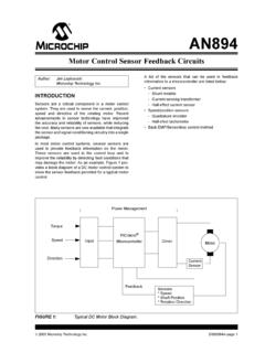
Motor Control Sensor Feedback Circuits
ww1.microchip.comvoltage drop across a known low value resistor is monitored in order to determine the current flowing through the load. If the resistor is small in magnitude, the voltage drop will be small and the measurement will not have a major effect on the motor circuit. The power dissipation of the resistance makes current shunts