Transcription of PVC Channel Site Sizable Series - Infinity Drain
1 PVC ChannelSite Sizable SeriesInstallation InstructionsThe site Sizeable Series intended for use with traditional waterproofing methods: Hot Mop Copper Pan Rubber Liner (Chloraloy ) PVC Liner Lead Pan FiberglassDimension are subject to Manufacturers tolerance and change without notice. We can assume no responsibility for use of superseded or void dimensiones est n sujetos a la tolerancia del fabricante y cambio sin previo aviso. No podemos asumir ninguna responsabilidad por el uso de datos a sustituir los nulos. S-TIF 6540S-TIF 6548S-TIF 6560S-TIF 6580S-TIF 6596S-TIF 65S-AG 3836S-AG 3848S-AG 3860S-AG 3896S-AG 38S-AG 10048S-AG 10096S-AG 100S-DG 3848S-DG 3860S-DG 3896S-DG 38S-DG 6548S-DG 6560S-DG 6596S-DG 65S-AG 6536S-AG 6548S-AG 6560S-AG 6596S-AG 65 Infinity Drain 18 Secatoag Avenue, Port Washington.
2 New York 11050 Phone Fax in the 38 SeriesA 3836 36 Stainless Steel GrateA 3848 48 Stainless Steel GrateA 3860 60 Stainless Steel GrateG 3836 36 PVC ChannelG 3848 48 PVC ChannelG 3860 60 PVC ChannelG 3896 96 PVC ChannelE 38 PVC Stop EndS 32 PVC Outlet SectionS 50 PVC Threaded OutletS-DG 65 SeriesD 6548 48 Stainless Steel GrateD 6560 60 Stainless Steel GrateG 6548 48 PVC ChannelG 6560 60 PVC ChannelG 6596 96 PVC ChannelE 65 PVC Stop EndS 50 PVC Threaded OutletS-AG 100 SeriesA 10048 48 Stainless Steel GrateG 10048 48 PVC ChannelG 10096 96 PVC ChannelE 100 PVC Stop EndS 50 PVC Threaded OutletS-DG 38 SeriesD 3848 48 Stainless Steel GrateD 3860 60 Stainless Steel GrateG 3848 48 PVC ChannelG 3860 60 PVC ChannelG 3896 96 PVC ChannelE 38 PVC Stop EndS 32 PVC Outlet SectionS 50 PVC Threaded OutletS-AG 65 SeriesA 6536 36 Stainless Steel GrateA 6548 48 Stainless Steel GrateA 6560 60 Stainless Steel GrateG 6536 36 PVC ChannelG 6548 48 PVC ChannelG 6560 60 PVC ChannelG 6596 96 PVC ChannelE 65 PVC Stop EndS 50 PVC Threaded OutletS-TIF 65 SeriesTA 6540 40 Stainless Steel GrateTA 6548 48 Stainless Steel GrateTA 6560 60 Stainless Steel GrateG 6540 40 PVC ChannelG 6548 48 PVC ChannelG 6560 60 PVC ChannelG 6580 80 PVC ChannelG 6596 96 PVC ChannelE 65 PVC Stop EndS 50 PVC Threaded NippleTIF PL TIF PlatesTKEY Lift Out KeySeries Components:Note.
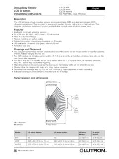
3 Installer must verify all rough-in dimensions prior to installation and consult local and national codes. Conformity and com-pliance to local and national codes are the responsibility of the en cuenta: Instala-dor debe comprobar todas las dimensiones en las par-tes previa a la instalaci n y consultar localmente y nacionalmente los c digos. La conformidad y el cum-plimiento de c digos local y nacional es responsabili-dad del instalador.*Not provided by Infinity Drain kitsKEY(A) Top Grate A38/D38/A65/TA65/A100(B) PVC Channel G38/G65/G100(C) Stop End E38/E65/E100(D) Outlet Section S32 (Not Applicable for AG65/DG65/TIF65/AG100)(E) Threaded Nipple - S50 (F65 non-threaded nipple, for no-hub installation )Weep HolesWaterproofing Membrane(F) 2 Throat Clamp Down Drain Body* ( Two Pieces)(F1)(F2)3S-AG38/S-DG38/S-AG65/S-D G65/S-AG100/S-TIF65 kits DO NOT include a mechanically fastening clamp down Drain due to the disparity of material of each consumer s existing plumbing.
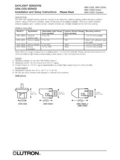
4 This is a standard item that is available through Infinity Drain or your local plumbing supply from various manufacturers (Oatey , Sioux Chief , JSC , PROFLO , Matco-Norca ).S-AG 38/S-DG38/S-AG65/S-DG65/S-AG100/S-TIF65 NO INCLUYE la sujeci n mec nica del drenaje por la raz n que var a el material de c digo local. Este drenaje es residencial que est disponible a trav s de Infinity Drain o su local suministro de plomer a de diversos fabricantes. ( Oatey , Sioux Chief , JSC , PROFLO , Matco-Norca ).2 clamp down Drain not included in kitAdd Clamp Down Drain :CDA 22 Clamp Down Drain ABSCDI 22 Clamp Down Drain Cast IronCDP 22 Clamp Down Drain PVCO ptional Components: (Not Included)F 65 PVC Non-Threaded OutletGAM 65 PVC 90 Angle JoinerTNRN-P PVC Threaded NippleF 100 PVC Non-Threaded OutletG38108 108 PVC ChannelUCP 2 Universal 2 Clamping PlateGJC 38 PVC Straight Joiner StripG65108 108 PVC ChannelUCP 4 Universal 4 Clamping PlateGAM 38 PVC 90 Angle JoinerGJ 100 PVC Straight Joiner StripERB Eccentric Reducer Bushing 4 x2 GJC 65 PVC Straight Joiner StripGA 100 PVC 90 Angle JoinerSection A-A S-AG 38, S-DG 381 "1 "1 "2 "6 "2"Section A-A S-TIF 651 " "2 "1 "2 "6 "2"Section A-A S-AG 65, S-DG 652 "2 "6 "2"1 "1 "1 "4 " "2 "6 "2"Section A-A S-AG 100 All drains can be adjusted upward for an additional 1 in PROCEDURE.
5 When Drain install is required to be flush against the finished wall, build out wall with backer board over round clamp down Drain body (F) to compensate for the Drain OPCIONAL:Cuando el drenaje sea instalado, se requi-ere que est completamente a la pared, construir la pared con m ltiples paneles de cemento sobre el redondo drenaje (F) para compensar el radial del Determine the location of the Drain outlet location. Typically linear drains span a dimen-sion from wall to wall, against a wall or at a shower entrance. 2. If clamp down Drain body (F) is not installed. Attach (F) to existing waste line and allow Drain body to recess into sub-floor. Ensure that Drain body (F) is level. Unscrew and remove top clamp down plate from Drain Spread a primary mortar bed across the intended shower area.
6 Pitch this bed in four directions towards the Drain body (F).4. When mortar layer is dry, perform necessary waterproofing (PVC Liner, CPE Rubber Liner/Chloraloy , Lead Pan, Copper Pan, Hot Mop, Fiberglass) as per local code. Ensure waterproofing layer reaches the edge of the hole in the Drain body (F). Reat-tach the top clamp down plate to the clamp down Drain body (F) over the waterproofing layer using Measure desired wall to wall length, allow for wall tile thickness and 3/16 for both stop ends (C). Cut PVC Channel (B) to desired n1. Determine la ubicaci n del emplazamiento del drenaje. T picamente el drenaje lineal atra-viesa una dimensi n de pared a pared, contra la pared, o en una entrada de un ba o. 2. Si el drenaje (F) no est instalado. Adjuntar el drenaje (F) a la l nea de residuos exis-tentes y permite el drenaje a que descanse en el piso.
7 Aseg rese, que el drenaje (F) este nivelado. Destornilla y remueve la placa de sujeci n de Esparcir una primaria de capa de mortero a trav s del destino o zona del ba o. Lanzar la capa de mortero en cuatro direcciones hacia el drenaje (F).4. Cuando la capa de mortero este seca, realice la impermeabilizaci n necesaria (Forro del PVC, cobre, panal de vidrio) seg n el c digo local. Asegura que la capa de impermeabilizaci n alcance al borde del agujero en el drenaje (F). Vuelva a colocar la placa de sujeci n de arriba al drenaje (F) sobre las capa de impermeabili-zaci n usando Medir la longitud deseada a pared a pared, permitir el espesor de la baldosa pared y 3/16 por ambas partes (C). Corte canal (B) a la desead EN CUENTA SOLO PARA S-AG38/S-DG38: Tener en cuenta en los dos 7/16 secci n (D) a lo largo del canal.
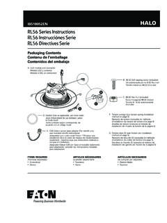
8 NOTE ONLY FOR S-AG38/S-DG38 Series : Account for the 2-7/16 outlet section (D) along Channel ONLY FOR S-AG38/S-DG38 Install: Cut the sized PVC Channel at the desired location of the outlet section. Insert the open ends of the PVC Channel (B) into the slotted ends of the outlet section (D) Dry fit components before affixing. Affix with clear PVC primer and PVC SOLO PARA S-AG38/S-DG38 INSTALA-CION: Corte el canal de PVC a la ubicaci n deseada a donde va ser la secci n de salida de agua. Pegar la parte (D) a la parte (B) del canal con PVC MembraneDouble Layer Backer Board(F) 2 Throat Clamp Down Drain Body* (Two Pieces)(F1)(F2)*Not provided by Infinity Drain kitsOPTIONAL PROCEDURE / PROCEDIMIENTO OPCIONAL56b. ONLY FOR S-AG65/S-DG65/S-TIF65/S-AG100 Install: Using a 2-1/4 hole saw, cut a hole through the base of the PVC Channel at the desired outlet location along the length of the Channel .
9 6b. SOLO PARA S-AG65/S-DG65/S-TIF/S-AG100 INSTALACION: Usando un 2-1/4 sier-ra de perforaci n, corte un agujero a trav s de la base del canal de PVC a la ubicaci n que desea a lo largo de la longitud del canal. Cordless Drill with 2 Hole Saw(B) PVC Channel G38/G1007. Dry fit components before affixing. Affix the stop ends (C) to the Channel using clear PVC primer and PVC Poner una tapa de PVC a cada esquina del canal usando imprimaci n PVC y cemento de PVC.(B) PVC Channel G38/G65/G100(C) Stop End E38/E65/E100 Note: Do NOT affix Channel or outlet sec-tion to threaded nipple until step en cuenta: No pege el canal a la sec-ci n de salida al niple roscado hasta el paso Screw threaded nipple (E) into top clamp down plate of the Drain body (F).
10 Adjust to the desired height. Turn clockwise to lower, counter-clockwise to Enroscar niple roscado (E) en la sujeci n superior del drenaje (F). Adaptarla a la altura que desea. Gire hacia la derecha para bajar, hacia izquierda para Test fit the combined PVC Channel for desired height onto the threaded nipple (E). Affix the threaded nipple (E) to the underside of the combined PVC Channel using clear PVC primer and PVC Pruebe y ajuste a la combinaci n de PVC a la desea longitud en el threaded nipple (E). Colocar el threaded nipple (E) en la parte inferior del canal de PVC usando impri-maci n PVC y cemento de PVC.(E) Threaded Nipple - S50(F) 2 Throat Clamp Down Drain Body* (Two Pieces)Waterproofing MembraneMortar BedSubfloor(F1)(F2)(B) PVC Channel G38 Desired Outlet Location32 Tooth per Inch Blade Hacksaw(D) Outlet Section S32(B) PVC Channel G386 Note: Minimum height: 1 Maximum height with standard nipple (S50): 2 Tenga en Cuenta: Altura M nima: 1 Altura M xima con niple: (S50): 2 PVC Channel AssemblyWaterproofing MembraneMortar BedSubfloorShimsLumberTileBacker Board10.