Transcription of INSTALLATION INSTRUCTIONS FOR DUCT SMOKE …
1 INSTALLATION INSTRUCTIONS FOR. duct SMOKE DETECTORS MOUNTED. ON COMBINATION FIRE/ SMOKE . OR SMOKE DAMPERS. Please reference SMOKE detector manufacturer's documen- To avoid stratification, detector placement should be such tation supplied with the damper for additional information. that there is a uniform airflow through the duct . Per NFPA. 72, detectors should be at least six duct widths down- ASSEMBLY APPROVAL stream from any duct openings, sharp bends or branch connectors. Underwriters Laboratories Inc. does not have a separate Prod- uct Category for factory mounted damper/ SMOKE detector as- DAMPERS AVAILABLE. semblies. Individually the SMOKE detector and the damper have been evaluated by their applicable UL Standards. It is The SMOKE detector models listed below can be provided the responsibility of the Local Authority Having Jurisdiction to with any of the following combination fire/ SMOKE damp- determine the appropriateness of the SMOKE detector/damper ers or SMOKE dampers: assembly taking into consideration design velocities during an incident condition and obstructions/ duct fittings in prox- Models FA-Series, FS-Series, FSM-Series, FS2C, imity of the SMOKE detector.
2 SA-Series, S-Series, TA-Series, FT-Series PURPOSE OF duct SMOKE DETECTION The detector can be provided one of two different ways. The detector can be factory mounted to the sleeve of the National and local safety standards and codes recognize the damper and factory wired to the damper actuator. When ability of air duct systems to transfer SMOKE , toxic gases, factory wired, the damper will travel to the fail position and flame from area to area. Sometimes SMOKE can be of when the detector senses SMOKE (electrical power dis- such quantity as to be a serious hazard to life safety unless connected). The detector can also be factory mounted blowers are shut down and dampers are actuated. The pri- to the sleeve of the damper but not wired to the damper mary purpose of duct SMOKE detection, then, is to prevent actuator. NOTE: Model 2151 must be factory wired. injury, panic, and property damage by reducing the spread (recirculation) of SMOKE .
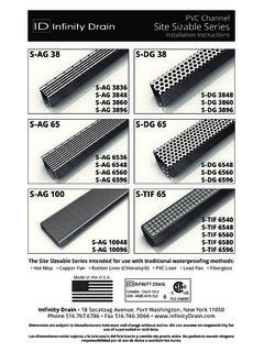
3 duct SMOKE detection can also duct DETECTORS AVAILABLE. serve to protect the air conditioning system itself from fire and SMOKE damage. Consult NFPA 90A, NFPA 72 and Local Air Balance offers two models of detectors each with spe- Codes to determine where SMOKE detectors are required. cific application requirements. TABLE ONE. DAMPER MINIMUM. MODEL SLEEVE DEPTH. FS-Series, FA-Series FT-Series, TA-Series SA-Series 20 . FSM. (Integral Sleeve). FS2C 15 with flange and 1 grille clearance 16 with flange and 3 grille clearance 18 without a flange S-Series 18 . Note: Additional sleeve length added to actuator (detector) side. abiair balance A Mestek Company EXTERNAL duct MOUNTED MODEL SM-501-P. This photoelectronic detector mounts externally to the duct with intake and exhaust sampling tubes penetrating into the duct . This detector is recommended for ducts, 6 inches and wider with duct velocities within the 500 fpm to 4000 fpm range.
4 Since this SMOKE detector is not rated for use at velocities below 500 fpm, local code may require an alternate means of damper closure such as zone detection or auto- mated damper closure when the system fan is shut down. The Local Authority Having Jurisdiction should be consulted EXTERIOR MOUNTED duct . prior to the INSTALLATION of the damper and SMOKE detector. DETECTOR AND WIRING. For proper air sampling, duct pressure should be a minimum ENCLOSURE (HOUSING EXTENDS. of inches of water. Standard location when factory BEYOND FRAME ON SHORT. HEIGHT DAMPERS. mounted will be on the side opposite the damper actuator. The inlet sampling tube is to be located between blades to avoid blockage of the airflow past the tube. If the detector is to be mounted on the actuator side then a longer damper 8 MINIMUM. DAMPER WIDTH. sleeve must be specified at time of order. Note: the damper 2.)
5 Sleeve can extend no more than 16 beyond the face of the fire barrier. Inlet sampling tube length and orientation are INLET. SAMPLING. critical for proper functioning. The inlet holes in the sampling 10 MIN. TUBE. DAMPER. tube must face into the airflow. The orientation of the inlet HEIGHT. 9 . tube can be easily site rotated for proper airflow orientation. Inlet sampling tube length requirements: INLET SAMPLING TUBE LOCATED. BETWEEN OPENED BLADES. DAMPER FRAME/SLEEVE. A. The inlet sampling tube must span the duct width. duct EXTERNAL ACTUATOR. widths must be known at time of order to insure that the MODEL SM-501-P. proper length of inlet sampling tube will be provided. See Table Two for appropriate sampling tube part number. B. Insure that the red end cap is installed in the end of the inlet sampling tube. C. For tubes longer than the width of the duct , the tube should extend out of the opposite side of the duct .
6 Trim the tube so two inches maximum extend outside of the duct with the extended end plugged and tape close any holes in the protruding section of the tube. GENERAL DESCRIPTION/SPECIFICATIONS TABLE TWO. duct INLET SAMPLING. Type: Photoelectronic SM-501-P WIDTH TUBE MODEL. Velocity Range: 500-4,000 fpm 6 to 12 Operating Temperature Range: 32 F to 100 F. 12 to 30 Operating Humidity Range: 10% to 85% Nominal Voltage: 30 to 60 230 VAC 50-60 Hz., 115 VAC 50-60 Hz., 60 to 120 24 VDC 50-60 Hz., 24 VAC 50-60 Hz. Contact Ratings: Alarm: 2 sets of Form C rated @10 Amps @ 115 VAC. Trouble: 1 set of Form C rated @10 Amps @ 115 VAC. Agency Listings: UL 268A; MEA Listed: 73-92-EX; Vol. 20. CSFM 3240-1004:108. ADDITIONAL INFORMATION. Reference SMOKE detector manufacturer's INSTRUCTIONS packaged with each detector for specific wiring instruc- tions, maintenance and testing information.
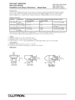
7 The model SM-501-P detector housing cover must be securely fas- tened to complete the air-tight enclosure for proper air sampling. INTERNAL duct MOUNTED MODEL 2151 ADDITIONAL INSTALLATION REQUIREMENTS. This photoelectronic detector mounts internally within ducts up to 18 inches in width. Since this detector is mounted These devices will not operate without electrical power. The within the duct , NFPA requires that means must be pro- Model SM-501-P detector housing is not weather proof and vided to monitor and test this detector from outside of the if specified, requires the WP-1 NEMA 3R weatherproof en- duct . To accomplish this requirement, a remote test sta- closure. Location of the detector must not interfere with the tion (Model RTS451) and a remote test coil kit (Model movement of the damper blades or the damper linkage. All RTC100) are provided, reference separate INSTRUCTIONS and wiring must be installed in compliance with the National the wiring schematic contained within this booklet.
8 duct Electrical Code and the local codes having jurisdiction. For velocity can range from 0 to 3000 fpm. For ducts wider signal wiring (the wiring between detectors or from detec- than 18 inches with velocities less than 500 fpm, it is rec- tors to auxiliary devices), it is usually recommended that ommended that multiple detectors 18 inches maximum on single-conductor wire be no smaller than 18 AWG. The center be installed. Standard location when factory mounted detector terminals accommodate wire sizes up to 14 AWG. will be the top inside of the damper sleeve. When a SMOKE detector is controlling a damper driven with a pneumatic actuator, the pneumatic actuator must be con- GENERAL DESCRIPTION/SPECIFICATIONS trolled by an E/P valve (solenoid). Type: Photoelectronic Velocity Range: 0-3,000 fpm Operating Temperature Range: 32 F to 120 F. Operating Humidity Range: 10% to 93% Nominal Voltage: MAINTENANCE AND SERVICE OF duct DETECTORS.
9 120 VAC (Requires Base No. B114LP). Remote testing: Requires remote test station SMOKE detectors are designed to be as maintenance free RTS451 and remote test coil kit RTC100 for each as possible. However, dust, dirt, and other foreign matter Model 2151 detector. can accumulate inside a detector and change its sensitiv- Contact Ratings: See information provided with each ity; this is especially true with duct type SMOKE detectors. detector. They can become more sensitive, which may cause un- wanted alarms, or less sensitive, which may reduce the level Agency Listings of protection. Both are undesirable. Therefore, detectors UL 268A, File S911 (N) (Requires remote test coil) should be tested periodically and maintained at regular in- RR 8281 (City of Los Angeles) tervals. Refer to Section 4-4 and Appendix B of NFPA-90A, CSFM 7272-1209:131 Chapter 7 of NFPA 72E.
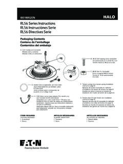
10 Additional Information: TYPICAL MAINTENANCE PRACTICES. Reference SMOKE detector manufacturers' INSTRUCTIONS Each INSTALLATION location must be assessed on its own mer- packaged with each detector for specific wiring instruc- its. If the protected area is of a very dirty nature, then the tions, maintenance and testing information. duct units will have to be checked and cleaned on a quar- TESTING AND MAINTENANCE: terly basis or when cleaning is required. As a guideline, the detector head should be cleaned every six months or as Reference SMOKE detector manufacturers' INSTRUCTIONS on required. Notify the proper authorities that the SMOKE de- field testing and recommended/required maintenance. tector system is undergoing maintenance, and therefore the system will be temporarily out of service. CAUTION: Dis- able the zone or system undergoing maintenance to prevent 8 MINIMUM unwanted alarms and possible dispatch of the fire depart- DAMPER WIDTH 4 x 4 STEEL.