Transcription of Quick Reference Install Guide Guide Translations ...
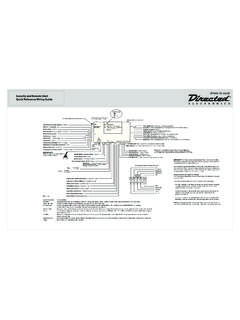
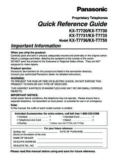
1 2013 Directed. All rights Reference Install GuideSecurity and Remote Start for:Responder HD, LCD, LED, 1-wayNeutral SafetySwitch1109876123451185113101218109 1112D2D Port (for external Xpresskit interface module)ONIMPORTANT! Neutral Safetyswitch must be plugged inand in the ON positionRF Portfor IVUC ontrol CenterThermistor/Temp SensorSensor 1 Bitwriter/SmartStart PortDoor Lock PortRemote Start10-pin HarnessMain 6-pin Harness10A FUSE MINI ATM RPN: 8540 LIGHT FLASH POLARITY (10A (MAXIMUM) FUSE JUMPER) Sensor 2 Aux/Shutdown/Trigger 24-pin HarnessGuide TranslationsFor a Spanish or French version of the Installation Guide , please download it from under Resources .Traducci n de los manuales:Para obtener una versi n en Espa ol o Franc s del Manual de Instalaci n, desc r-guela de bajo el t tulo Recursos ( Resources ).
2 Traduction du Guide :Pour une version fran aise ou espagnole du Guide d installation, veuillez le t -l charger sous Resources ..Bitwriters with a date code of 6a or older require an IC upgrade (p/n 998M). Some bitwriters with a date code of 6B do not require the IC upgrade, refer to tech tip # 1112 for more information. The Bitwriter (p/n 998U) requires chip version or newer to program this PointsAdjusting the SensorAdjusting the sensor: Important! Make sure the vehicle is disarmed. The shock sensor sensitivity can be adjusted by using a trimmer tool to turn the the potentiometer clockwise to increase sensitivity and counterclockwise to de-crease : You can test the new setting by cautiously impacting the vehicle with increas-ing intensity while noting the LED status on the shock sensor.
3 When testing the sensor: warn away trigger is indicated by a short LED flash and full trigger is indicated by a longer LED the Tach (not needed with Virtual Tach)To learn the tach signal:1. Start the vehicle with the Within 5 seconds, press and hold the Control After 3 seconds the status LED on your Control Center lights constant when the tach signal is Release the Control : This unit can learn the tachometer with the analog input or through d2d using an interface module. The unit confirms which source is used by flashing the parking lights. When programming tach learning with: Analog, the parking lights flash one time. D2D interface module, the parking lights flash the tachometer input on the system is connected to the vehicle, the d2d tachometer input is Virtual Tach (not needed with hard-wired tach inputs)To program Virtual Tach:1.
4 After the Install is complete, remote start the engine. The programming op-eration may require 3 cranks of the starter before the engine starts and runs. Do not turn off the remote start if this happens, it is a normal programming Once the engine begins running, let it run for at least 30 Using the Remote, send the Remote start command to turn remote start off. Virtual Tach is programmed. To reset Virtual Tach, go into the Remote Pairing section of this Guide and press/re-lease the Control button 4 times for step #4, then press and hold the Control button to reset Virtual Tach. Virtual Tach cannot be reset with the : Virtual Tach cannot be used in MTS Manual Transmission Mode. It is also not recommended for diesel vehicles. Virtual Tach handles disengaging the starter motor during remote starting it does not address over-rev.
5 If the customer wants to have the over-rev protection capability, the tach wire must be connected. Important: After successfully learning Virtual Tach, a small minority of ve-hicle starters may over crank or under crank during remote start. The Bit-writer can be used fine tune the starter output time in 50 ms increments to compensate for such an occurrence. Remote Start Shutdown/Startup DiagnosticsTo perform shutdown diagnostics:1. With the ignition Off, press and hold the Control button (on Control Center).2. Tu r n the ignition On and then back Off while holding the Control Release the Control Press and release the Control button. The status LED flashes to report the last shutdown for one minute or until the ignition is turned on, as shown in the following table:Status LED Flashes Shutdown Mode1 flash Runtime expired 2 flashes Over-rev shutdown 3 flashes Low or no RPM4 flashes Transmitter shutdown (or optional push button)5 flashes (+) Brake shutdown 6 flashes Hood shutdown7 flashes Timer mode/Turbo mode/Manual mode error *8 flashes Neutral safety shutdown9 flashes Low battery (voltage mode)10 flashes Alarm triggered **11 flashes Wait-to-start input timed out * Timer mode error: Ignition is on or shutdown input is active when activating timer mode.
6 Turbo mode error: Turbo mode is programmed off, engine is not on or shut-down input is active. Manual mode error: MTS mode not enabled.** Alarm was triggered during remote start sequence. Startup Diagnostics: If the vehicle fails to activate the remote start, the remote start module will notify you via parking light flashes on the vehicle to identify the no-start Light Flashes5 flashes Brake wire is active6 flashes Hood pin wire is active7 flashes Manual transmission mode is enabled and not flashes Neutral safety wire has no ground or the neutral safety switch is of ZonesA zone is represented by the number of status LED flashes used by the system to identify a particular type of Description1 Trunk Pin24 pin Blue wire2 Instant trigger: a heavier impact detected by the shock sensorShock switch trigger24 pin Green or Violet wire4 Instant trigger.
7 For optional sensorsOptional MUX port5 Ignition triggerHeavy gauge 10 pin Pink wire6 Hood Pin24 pin Grey wireBitwriter - Only OptionsIf programming with the Bitwriter , the learn routine can be locked or un-locked. If the learn routine has previously been locked, it must be unlocked with Bitwriter - this cannot be done manually with the Control Bitwriter gives you access to a wider range of system options. These features and the adjustments that may be programmed are described under the Bitwriter section in the full online Guide . See full Installation Guide for more detailed information. Such informa-tion and more can be found online at: : If the IVU (control center) has been replaced, all remote controls must be re-paired with the system. See Remote Pairing for details. Wiring ConnectionsMain Harness, 6-pin connector1 RED(+)12 VDC CONSTANT INPUT2 BLACK(-) CHASSIS GROUND3 BROWN(+) SIREN OUTPUT 4 WHITE/BROWNPARKING LIGHT ISOLATION WIRE - PIN 87a of onboard relay5 WHITE PARKING LIGHT OUTPUT 6 ORANGE(-) 500mA GROUND WHEN ARMED OUTPUTDoor Lock, 3-pin connector1 BLUE(-) 500mA UNLOCK OUTPUT2 EMPTYNOT USED3 GREEN (-) 500mA LOCK OUTPUTR emote Start, 10-pin heavy gauge connector1NC No Connection2 RED/BLACK(+) FUSED 12V ACCESSORY/STARTER INPUT3 PINK/BLACK(+) FLEX RELAY INPUT 87A key side (if required) of FLEX RELAY4 PINK/WHITE(+) IGNITION 2 / FLEX RELAY OUTPUT5 RED(+) FUSED 12V IGNITION 1 INPUT6 GREEN(+) STARTER INPUT (KEY SIDE OF THE STARTER KILL)7 VIOLET(+) STARTER OUTPUT (CAR SIDE OF THE STARTER KILL)8 ORANGE(+) ACCESSORY OUTPUT9 RED/WHITE(+)
8 FUSED 12V IGNITION 2 / FLEX RELAY INPUT 8710 PINK(+) IGNITION 1 INPUT/OUTPUTA uxiliary/Shutdown/Trigger Harness, 24-pin connector1 PNK/WHITE(-) 200mA Ignition 2/Flex OUTPUT2 BLUE/WHITE(-) 200mA 2ND STATUS /REAR DEFOGGER OUTPUT3 RED/WHITE(-) 200mA TRUNK RELEASE OUTPUT4 BLACK/YELLOW(-) 200mA DOME LIGHT OUTPUT5 DARK BLUE(-) 200mA STATUS OUTPUT6 WHITE/BLACK(-) 200mA AUX 3 OUTPUT7 WHITE/VIOLET(-) 200mA AUX 1 OUTPUT8 ORANGE/BLACK(-) 200mA AUX 4 OUTPUT9 GRAY(-) HOOD PIN INPUT (NC OR NO)10 BLUE(-) TRUNK PIN/INSTANT TRIGGER INPUT (N/C OR N/O)11 WHITE/BLUEACTIVATION INPUT12 VIOLET/WHITE*TACHOMETER INPUT13 BLACK/WHITE**(-) NEUTRAL SAFETY /PARKING BRAKE INPUT14 GREEN/BLACK (-) 200mA FACTORY ALARM DISARM OUTPUT15 GREEN*(-) DOOR INPUT16 BROWN/BLACK(-) 200mA HORN HONK OUTPUT17 PINK(-) 200mA IGNITION 1 OUTPUT18 VIOLET*(+) DOOR INPUT19 VIOLET/BLACK(-) 200mA AUX 2 OUTPUT20 BROWN(+) BRAKE SHUTDOWN INPUT21 VIOLET/YELLOW(-) 200mA STARTER OUTPUT22 GRAY/BLACK (-) DIESEL WAIT TO START INPUT23 ORANGE(-) 200mA ACCESSORY OUTPUT24 GREEN/WHITE(-) 200mA FACTORY ALARM ARM OUTPUT* Required connection for manual transmission vehicles.
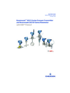
9 ** Ground this wire for automatic transmission vehicles or connect to the park-ing brake wire for manual transmission vehicles (see owners Guide for man-ual transmission procedure).Important: NEVER connect 200mA low current outputs directly to a motor or high current device WITHOUT a relay135 INSERTION/WIRE SIDE2462423 PINK/WHITEVIOLET/WHITEGREEN/WHITEBLACK/W HITE123 INSERTION/WIRE SIDE132412 PINK/WHITEVIOLET/WHITEGREEN/WHITEBLACK/W HITE 2013 Directed. All rights 2013-08 Programming System FeaturesThe System Features Learn Routine dictates how the unit operates. It is possible to access and change most of the feature settings using the Control button. 1. Open a door. 2. Tu r n the ignition on, then off. 3. Select a Menu. Press and hold the Control button. The number of siren chirps indicates the menu number.
10 1 chirp indicates menu 1, 2 chirps - menu 2 and 3 chirps for menu When the desired menu chirps are heard, release the Control Select a Feature. Press and release the Control button the number of times corresponding to the feature you wish to change. Then press and hold one more time to select the Program the Feature. While holding the Control button, you can program the feature using the remote control. For features with only two options; AUX = option 1 while AUX = option 2. For features with more than two options; AUX selects the options in ascending order, while AUX selects them in descending : Pressing AUX button resets the feature to the factory a feature is programmed: Other features can be programmed within the same menu Another menu can be selected The learn routine can be exited if programming is completeTo access another feature in the same menu:1.