Transcription of Valet switch Control button LED Status LED Quick …
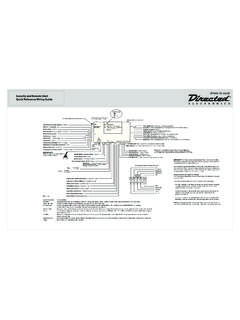
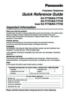
1 2009 Directed Electronics. All rights reference Install GuideRemote Start w/ Keyless Entry1-Way SuperCodeCPU110A FUSEMINI ATMRPN: 8540 LIGHT FLASH POLARITY(10A (MAXIMUM) FUSE JUMPER) + -58761234 BitwriterPortNeutral SafetySwitchHorn InputPolarity Jumper11098761234511851131012181091112D2 D Port (for external Xpresskit interface module)10A FUSE MINI ATM RPN: 8540 LIGHT FLASH POLARITY (10A (MAXIMUM) FUSE JUMPER) + -ONIMPORTANT! Neutral Safetyswitch must be plugged inand in the ON positionD2D jumpers; Factory setting is horizontal position. Most Xpresskit modules use this setting, check the Xpresskit installation guide for the specific Portfor IVUC ontrol CenterTemperatureSensor+ -10A FUSEMINI ATMRPN: 8540 LIGHT FLASH POLARITY(10A (MAXIMUM) FUSE JUMPER) + -091110060807226688771111011110995512124 433 ELECTRONICSR3142 TACH LEARN THREASHOLDJMP1 OFFONCPU1 NOTE: Pin 1 is on the leftTACH threshold OFF:TACH threshold ON:BitwriterPortNeutral SafetySwitchRemoteStart InStatus LEDV aletPortDoor Lock/Unlock OutputRelay OutPortH2 Port11098761234511851131012To changejumpersettings112 CPU110A FUSEMINI ATMRPN: 8540 LIGHT FLASH POLARITY(10A (MAXIMUM) FUSE JUMPER) + -58761234 BitwriterPortNeutral SafetySwitchHorn InputPolarity Jumper11098761234511851131012181091112D2 D Port (for external Xpresskit interface module)10A FUSE MINI ATM RPN.
2 8540 LIGHT FLASH POLARITY (10A (MAXIMUM) FUSE JUMPER) + -ONIMPORTANT! Neutral Safetyswitch must be plugged inand in the ON positionD2D jumpers; Factory setting is horizontal position. Most Xpresskit modules use this setting, check the Xpresskit installation guide for the specific Portfor IVUC ontrol CenterTemperatureSensorNew FeaturesEnhanced Tach Filtering Addition of Aux 4 for a total of 5 Channel Outputs New 18 pin Harness Improved current capable Aux & Factory Alarm Outputs Enhanced Temperature Reading 10A FUSEMINI ATMRPN: 8540 LIGHT FLASH POLARITY(10A (MAXIMUM) FUSE JUMPER) + -091110060807226688771111011110995512124 433 ELECTRONICSR3142 TACH LEARN THREASHOLDJMP1 OFFONCPU1 NOTE: Pin 1 is on the leftTACH threshold OFF:TACH threshold ON:BitwriterPortNeutral SafetySwitchRemoteStart InStatus LEDV aletPortDoor Lock/Unlock OutputRelay OutPortH2 Port11098761234511851131012To changejumpersettings112 CPU110A FUSEMINI ATMRPN.
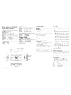
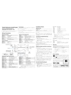
3 8540 LIGHT FLASH POLARITY(10A (MAXIMUM) FUSE JUMPER) + -BitwriterPortNeutral SafetySwitchStatus LEDV aletPort11098761234511851131012 TACH threshold OFF:TACH threshold ON:To changejumper settings181091112D2D Port (for external Xpresskit interface module)Optional Mux Port(for additional sensors)10A FUSE MINI ATM RPN: 8540 LIGHT FLASH POLARITY (10A (MAXIMUM) FUSE JUMPER) + -ONIMPORTANT! Neutral Safetyswitch must be plugged inand in the ON positionD2D jumpers; Factory setting is horizontal position. Most Xpresskit modules use this setting, check the Xpresskit installation guide for the specific Portfor IVUW iring ConnectionsMain Harness (H1), 12-pin connectorH1/1 RED/WHITE(-) 200mA TRUNK RELEASE OUTPUTH1/2 RED(+)12 VDC CONSTANT INPUTH1/3 BROWN(-) 200mA HORN HONK OUTPUT H1/4 WHITE/BROWNLIGHT FLASH ISOLATION WIRE - PIN 87a of onboard relayH1/5 BLACK(-) CHASSIS GROUNDH1/6 VIOLET(+) DOOR TRIGGER INPUTH1/7 BLUEFACTORY HORN INPUT (Use jumper to set polarity)H1/8 GREEN(-) DOOR TRIGGER INPUT (N/C or N/O)H1/9 BLACK/WHITE(-) 200mA DOME LIGHT OUTPUTH1/10 WHITE/BLUE(-) REMOTE START/ TURBO TIMER ACTIVATION INPUTH1/11 WHITE PARKING LIGHT OUTPUT H1/12 ORANGE(-) 500mA GROUND WHEN ARMED OUTPUTR emote Start, (H3) 8-pin connectorH3/1 PINK(+) IGNITION 1 INPUT/OUTPUTH3/2 RED/WHITE(+) 12 VDC CONSTANT INPUT for ignition 2 and flex relaysH3/3 ORANGE(+) ACCESSORY OUTPUTH3/4 VIOLET(+) STARTER OUTPUT H3/5 RED(+)
4 12 VDC CONSTANT INPUT for ignition 1 relayH3/6 PINK/WHITE(+) IGNITION 2 / FLEX RELAY OUTPUTH3/7 PINK/BLACK(+) FLEX RELAY INPUT 87A key side (if required) of FLEX RELAYH3/8 RED/BLACK(+) 12 VDC CONSTANT INPUT for Acc and starter relaysDoor Lock, 3-pin connector1 BLUE500mA (-) UNLOCK OUTPUT2 EMPTYNOT USED3 GREEN 500mA (-) LOCK OUTPUTH2 Harness, 18-pin connectorH2/1 LIGHT GREEN/BLACK(-) 200mA FACTORY ALARM DISARM OUTPUTH2/2 ORANGE/BLACK(-) 200mA AUX 4 OUTPUTH2/3 GREEN/WHITE(-) 200mA FACTORY ALARM ARM OUTPUTH2/4 VIOLET/BLACK(-) 200mA AUX 2 OUTPUTH2/5 WHITE/BLACK(-) 200mA AUX 3 OUTPUTH2/6 WHITE/VIOLET(-) 200mA AUX 1 OUTPUTH2/7 GREY/BLACK(-) DIESEL WAIT TO START INPUTH2/8 EMPTYH2/9 VIOLET/WHITETACHOMETER INPUTH2/10 DARK BLUE(-) 200mA Status OUTPUTH2/11 PINK/WHITE(-) 200mA FLEX RELAY Control OUTPUTH2/12 ORANGE(-) 200mA ACCESSORY OUTPUTH2/13 PURPLE(-) 200mA STARTER OUTPUTH2/14 PINK(-) 200mA IGNITION 1 OUTPUTH2/15 GREY(-) HOOD PIN INPUT (NC OR NO)H2/16 BLUE/WHITE(-) 200mA 2ND Status /REAR DEFOGGER OUTPUTH2/17 BROWN(+) BRAKE SHUTDOWN INPUTH2/18 BLACK/WHITE(-) NEUTRAL SAFETY INPUTB itwriters with a date code of 6a or older require an IC upgrade (p/n 998M).
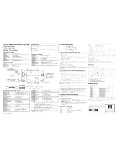
5 Some bitwriters with a date code of 6B do not require the IC upgrade, refer to tech tip # 1112 for more information. The Bitwriter (p/n 998U) requires chip version or newer to program this PointsValet switchLED Control buttonStatus LED Control CenterControl CenterControl CenterControl CenterControl CenterValet switchLED Control buttonStatus LED Control CenterLearning the Tach (not needed with Virtual Tach)To learn the tach signal:Start1. the vehicle with the 5 seconds, 2. press and hold the Control 3 seconds the Status LED on your Control Center lights constant when 3. the tach signal is the Control Virtual Tach (not needed with hardwire tach inputs)To program Virtual Tach:After the install is complete, 1. remote start the engine. The programming op-eration may require 3 cranks of the starter before the engine starts and runs. Do not turn off the remote start if this happens, it is a normal programming the engine begins running, let it run for at least 30 Using the Remote, send the Remote start command to turn remote start off.
6 3. Virtual Tach is programmed. To reset Virtual Tach, go into the Remote Pairing section of this guide and press/re-lease the Control button 4 times for step #4, then press and hold the Control button to reset Virtual Tach. Virtual Tach cannot be reset with the : Virtual Tach cannot be used in MTS Manual Transmission Mode. It is also not recommended for diesel trucks. Virtual Tach handles disengaging the starter motor during remote starting it does not address over-rev. If the customer wants to have the over-rev protection capability, the tach wire must be connected. Important: After successfully learning Virtual Tach, a small minority of ve-hicle starters may over crank or under crank during remote start. The Bit-writer can be used to fine tune the starter output time in 50mS increments to compensate for such an occurrence. Remote Start Shutdown/Startup DiagnosticsTo perform shutdown diagnostics:With the ignition Off, 1.
7 Press and hold the Control the ignition On and then back Off while holding the Control the Control and release the Control button . The Status LED flashes to report the last shutdown for one minute or until the ignition is turned on, as shown in the following table: Status LED Flashes Shutdown Mode1 flash Runtime expired 2 flashes Over-rev shutdown 3 flashes Low or no RPM4 flashes Transmitter shutdown (or optional push button )5 flashes (+) Brake shutdown 6 flashes (-) Hood shutdown7 flashes Timer mode/Turbo mode/Manual mode error *8 flashes Neutral safety shutdown9 flashes Low battery (voltage mode)11 flashes Wait-to-start input timed out * Timer mode error: Ignition is on or shutdown input is active when activating timer mode. Turbo mode error: Turbo mode is programmed off, engine is not on or shut-down input is active. Manual mode error: MTS mode not Diagnostics: If the vehicle fails to activate the remote start, the remote start module will flash the parking lights on the vehicle to notify you of what caused the no-start Light Flashes5 flashes Brake wire is active6 flashes Hood pin wire is active7 flashes Manual transmission mode is enabled and not flashes Neutral safety wire has no ground or the neutral safety switch is PairingPrepare the vehicle system to be Paired with a new remoteTurn1.
8 The key to the ON position. Within 5 seconds 2. press and release the Control button on the system s Control Center one 5 seconds, 3. press and hold the Control button on the Control Center. The Status LED will flash one time and the horn honks to confirm the vehicle is ready for remote the Control button and proceed : If no remote pairing results, the system will exit after 60 seconds. Prepare the new remote to be Paired with the systemRemote Pair matches your remote to the system. Make sure the remote is set for the desired Car 1 (Default) or Car 2 operation for the system it will be paired with. Press1. and hold the AUXbutton for 8 seconds. Wait for the Transmit LED to light solid. 2. Release the AUXbutton. Press3. the AUX for 1 second. The transmit LED will blink 3 5 seconds, 4. press the AUX button . The vehicle horn will honk. You have now successfully learned the remote to the 5.
9 Vehicle remote start the AUX button two times to exit learn routine on the remote. The transmit LED will turn off and Remote FunctionsButtonLevelDIRECT ACCESSA U XX 1A U XX 2A U XX 3A U XX 4A U XLOCKSILENT LOCKA U XUNLOCKSILENT UNLOCKREMOTE VALETCAR FINDERA U XREMOTE STARTRUNTIME RESETTIMER MODESMART STARTREAR DEFOGGERAUXTRUNK RELEASEAUX 1 AUX 2 AUX 3 AUX 4A U XFUNCTION SHIFTSee full Installation guide for more detailed information on this system. Such information and more can be found online at: , Direct ed Electronics Logo, Direct ed with designed in Logo, Direct ed with Distributed Direct ed Logo Usage 2009 Directed Electronics. All rights 2010-01 Programming System FeaturesThe System Features Learn Routine dictates how the unit operates. It is possible to access and change most of the feature settings using the Control button . Turn1. the ignition on, then off. Select2.
10 A Menu. Press and hold the Control button . The number of horn honks and LED flashes indicates the menu number. 1 horn honk and LED flash indicates menu 1, 2 horn honks and LED flashes - menu 2 and 3 horn honks and LED flashes for menu the desired menu horn honks are heard with LED flashes, 3. release the Control a Feature. Press and release the Control button the number of times corresponding to the feature you wish to change. Then press and hold one more time to select the the Feature. While holding the Control button , you can program the feature using the remote Control . For features with only two options; AUX = option 1 while AUX = option 2. For features with more than two options; AUX selects the options in ascending order, while AUX selects them in descending : Pressing AUX button resets the feature to the factory a feature is programmed:Other features can be programmed within the same menu Another menu can be selected The learn routine can be exited if programming is complete To access another feature in the same menu:Press1.