Transcription of Repair Information - Eaton
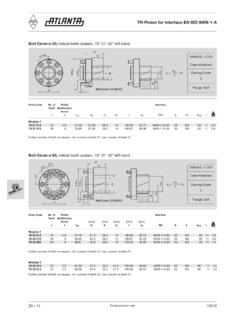
1 Char-Lynn . April, 1997. Hydraulic Motor Repair Information 10 000 Series Geroler Motors 002 003 004. Disc Valve Hydraulic Motor 10 000 Series Geroler Motors Parts Drawing 1. See Note 2 22. Page 3 13. 1. 9. See Note 2. 37 Page 3. B 23. 1-1/4 Split 24 14. 36. Flange Ports 3. 38 35 1 4. 3. 6. 7. 8 C Standard Motor 16. 5 40. 17. 18. 15 See Note 2. 20. 19 Page 4. 32. 31. 30. 32 and 34. 39 37. A. 13 1-5/16 36. O-ring Ports 38 35. 27. 13. 28. -002. 25 -003. 21. 13. 14. 14. Bearingless Motor Flange Replacement Part Below -004. 14. 3. 4. 3. ZZ. D Wheel Motor 2 Bearingless Motor 2. Disc Valve Hydraulic Motor 10 000 Series Geroler Motors Ref. Ref. No. Description No. Description 1 Shaft S/A 23 Washer, Rear Thrust 2 Flange, Mounting /Wear Plate 24 Bearing, Rear Thrust 3 Bearing, Radial 25 Geroler 4 Spacer, Bearing 27 Plate, Valve 5 Spacer, Bearing Front 28 Drive, Valve 6 Whasher, Thrust 30 Seal, Outer Face 7 Bearing, Front Thrust 31 Seal, Inner Face 8 Whasher, Thrust (Thin) 32 Spring, Compression 9 Plug/O-ring S/A 33 and 34 Balance Ring/Pin Assembly 13 O-ring (Note 1) 35 Ball 14 O-ring (Note 1) 36 Spring, Compression 15 Retainer, Front 37 Plug/O-ring S/A.
2 16 O-ring 38 Plug/O-ring S/A. 17 Ring, Quad 39 Valve 18 Washer, Backup 40 Screw, Cap (replaces and interchanges with studs). 19 Seal, Dust A Kit, Housing, Valve (1-5/16 O-ring Ports). 20 Screw, Cap B Kit, Housing, Valve (1-1/4 Split Flange Ports). 21 Drive, Main C Kit, Housing, Bearing (Std. Motor). 22 Plate, Wear D Kit, Housing, Bearing (Whl. Motor). Note 1: The -002 and -003 Bearingless motors use 4 O-rings while -004 motor uses 3 O-rings. Note 2: DO NOT use spacer with current replacement shafts (Ref. No. 1). Motors with this shaft spacer will still have to be reassembled with spacer unless the shaft was damaged and must be replaced. See pages 10 and 11 for wheel motor and bearingless motor Repair Small screwdriver (150 mm [6 in.] 200 mm [8 in.] long, Information . 6,3 mm [.25 in.] blade). Tools required for disassembly and reassembly are: Plastic or rubber hammer Torque wrench (170 Nm [1500 in-lb or 125 ft- lb] The following tools are not necessary for disassembly and capacity) reassembly, but are extremely helpful.
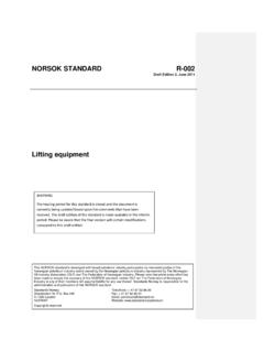
3 1, 15/16, 1/2, and 5/16 inch sockets Seal sleeve or bullet 300 mm [12 in.] - 400 mm [16 in.] breaker bar Alignment studs (2) if required * Motors with tie bolts and original studs not available. Alignment Studs (2). 241,0. [ ] 25,5. 12,7 [.50]. [ ]. 12,7 [.50] 15,87 [.625] Dia. Steel Rod Grind Flat Spots on Each Side 5/8-18 UNF. 3. Disc Valve Hydraulic Motor 10 000 Series Geroler Motors Disassembly Cleanliness is extremely important when repairing a hydraulic motor. Work in a clean area. Before disconnecting the lines, clean the port area of the motor thoroughly. Use a wire brush to remove foreign material and debris from the exterior joints of the motor. Check the shaft and keyway, remove all nicks, burrs, or sharp edges that might damage the shaft seals when installing the retainer over the shaft. Before starting the disassembly procedures, drain the oil from inside the motor.
4 Figure 2. Line Scribed for reassembly 2 Remove 4 bolts (or nuts and washers for earlier models) from motor. Remove studs (earlier models) per step 17. 3 Carefully lift the valve housing straight off. If this is done carefully, the springs and balance ring assembly will remain on the valve for easy removal. 4 Remove 2 check valve plug assemblies (plugs, springs, and steel balls) from valve housing. 5 Place valve housing on bench with open end up, then carefully remove 108 mm [ in.] seal, and 9,4 mm[.37 in.] seal. Motors with Studs Balance Ring Valve Ass'y Spring (4) Drive Balance Ring Figure 1. 1 Place the motor in a vise with the output shaft down, or place the motor (earlier models with studs) on a smooth, clean, flat surface; use a piece of wood under the center section of the motor to raise the valve Inner Outer housing end of the motor off the surface of your work area, see Fig.
5 1, Seal Seal Valve Valve Plate for these preparations. Figure 3. Note: It may be helpful for reassembly to scribe a line across the length of the motor. Although not all drawings show the motor in a vise, we recommend 6 Remove 4 balance ring assembly springs. that you keep the motor in the vise during disassembly and reas- 7 Remove balance ring assembly. sembly. Follow the clamping procedures explained throughout the manual. 8 Remove inner and outer seals from balance ring. 4. Disc Valve Hydraulic Motor 10 000 Series Geroler Motors Disassembly Studs (4) (earlier models only). 9 Remove valve. 10 Remove valve plate. 11 Remove valve drive. Seals Geroler Seals Spacer Figure 6. 17 Use a stud remover or vise grips to remove studs (earlier models only) see Fig. 6. 18 Remove 9,4 mm[.37 in.] seal, and 108 mm [ in.] seal from bearing housing.
6 Seals 19 Remove spacer from inside output shaft. Figure 4. Note: Some units have shafts with a raised area at bottom of splined cavity and do not use spacer. 12 Remove Geroler. Retain rollers in Geroler assembly. 13 Remove 9,4 mm[.37 in.] seals, and 108 mm [ in.] seals from the Geroler, 2 seals on each side of the Geroler. Splined Wear Thrust Drive Plate Washer Soft Pad Thrust Bearing Figure 5. 14 Remove splined drive from bearing housing. Figure 7. 15 Remove wear plate. 20 Place bearing housing in vise, as shown in Figure 7. Loosen 8 cap 16 Remove thrust bearing and thrust washer from wear plate. screws (5/16 inch) in retainer. 5. Disc Valve Hydraulic Motor 10 000 Series Geroler Motors Disassembly Cap Retainer Seal Output Shaft Plug Screw (8) Assembly Thrust Bearing Spacer Washers Plug Assembly Thrust Bearing Figure 9.
7 Dust Back-up Quad Seal Washer Seal Figure 8. 21 Place bearing housing on a clean, flat surface. Remove 8 cap 23 Remove output shaft. screws and retainer. 24 Remove 2 thrust washers and thrust bearing from the output shaft. 22 Remove quad-ring seal, back-up washer, 0-ring seal, and dust seal from retainer. Use a small screw- driver to remove the dust seal. Do 25 Remove bearing spacer. not damage bore of retainer. 26 Remove 2 plug assemblies (1 inch) from the bearing housing. Note: The bearing housing and bearings inside the housing are not sold separately. These bearings are hydraulicly pressed into the bearing housing. Reassembly Check all mating surfaces. Replace any parts that have scratches or burrs that couId cause leakage. Clean all metal parts in clean solvent. Blow dry with air. Do not wipe with a cloth or paper towel because lint or other matter can get into the hydraulic system and cause damage.
8 Output Shaft Plug Do not use coarse grit or try to file these parts. Check around the Assembly keyway and chamfered area of the shaft for burrs nicks or sharp edges that can damage the seals when reassembling the retainer. Bearing Spacer Note: Lubricate all seals with petroleum jelly such as Vaseline. Refer to the parts list (6-119) for replacement parts and proper seal kit number. Plug Assembly Figure 10. 6. Disc Valve Hydraulic Motor 10 000 Series Geroler Motors 6 Install back-up washer, quad ring seal, and 3-1/2 seal in the retainer. Apply petroleum jelly to inside diameter of dust seal and quad Resassembly ring seal. 7 Before installing retainer, place a protective sleeve or bullet, if I Place bearing housing on a smooth, flat surface. Install 2 plug available, over shaft. To prevent damage to seals, install retainer over assemblies, see Figure 10.
9 Tighten to 100 Nm[900 lb-in or 75 lb-ft]. shaft with a twisting motion. Do not cut or distort retainer seals. Damage to these seals will cause external leakage. 2 Install bearing spacer in bearing housing. 3 Install output shaft. Rotate shaft while instaling in bearing housing. 1. Thickest Washer 3 8. 5 6. Thrust Washers 7 4. 2. Torquing Sequence Figure 13. Thrust Bearing 8 Lubricate threads of 8 cap screws with a light film of oil. Install Figure 11 and finger tighten screws. Place unit in a vise, as shown in Figure 7. Tighten cap screws to 34 Nm [300 lb-in] of torque in the sequence shown in Figure 13. 4 Install 2 thrust washers and thrust bearing. Install thrust bearing between the 2 thrust washers, thickest washer over shaft first, see 9 Install key (when used) in key slot of shaft. Figure 11. 10 Reposition motor in vise, clamp housing flange, as shown in Fig.
10 1. Dust Seal 11 Pour a small amount of hydraulic oil inside outnut shaft. O-ring Back-up Washer Quad Seal Stud (4) (earlier models only). Retainer Seal Replacement Seals Spacer Figure 12. Figure 14. Note: Spacers are not used on units that have a raised area at bottom 5 Use a small press, if available, to install dust seal in retainer. Metal of splined cavity. side of dust seal must face toward retainer, as shown in Figure 12. If a press is not available, use a plastic or rubber hammer to tap dust seal 12 Install spacer in output shaft, guide spacer with a pencil. in place. 7. Disc Valve Hydraulic Motor 10 000 Series 18 Install splined drive in output shaft. For 345 cm3/r [ in3/r]. Geroler Motors displacement motor insert longer splined end of drive first, see Fig. 16. Resassembly 19 Apply petroleum jelly on 2 seals 9,4 mm[.]