Transcription of Repair Information - Eaton
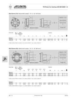
1 Char-Lynn . November, 1996. Power Steering Repair Information OUT. AUX. IN. OUT. AUX. IN. 217 Series and 227 Series Torque Generators 002. 2. Power Steering 217 Series Torque Generators 9. 10. 9. 700 8. 11. 15. 13. 18a 2a 14. 16. 18. 9. 17. 20. 12. OUT. AUXI. N. 5. 1. 19. 2 26. OUT. OUT. 6 28. 22 27 AUX AUX. IN IN. 3. 4. 9 12a 7. 21. 30. 1 Screw, Cap, (7) 15 Pin 2 Housing, Power End 16 Spring, Centering (for Standard Input Torque) (6). 2a Housing, Power End (bearings, needle type) 17 Ring, Retaining 3 Washer 18 Seal, Quad 4 Ring, Retaining 18a Seal, Shaft (Lip Type). 5 Seal, Quad 19 O-ring (2). 6 Shaft, Power End 20 Washer 7 Drive, Power End 21 Plate, Spacer 8 Plate, Spacer 22 Washer 9 Seal, O-ring (4) 26 Relief Valve S/A.
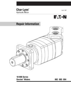
2 10 Gerotor 27 Plug 11 Drive, Control End 28 O-ring 12 Housing, Valve 30 Spacer, Spring (for Increased Input Torque) (4). 12a Housing, Valve (for Inlet Relief Valve) 700 Key, Woodruff (2). 13 Sleeve 14 Spool 3. Power Steering 227 Series Torque Generators 9. 10. 9. 8. 700 11. 15. 2a 13. 18a 14. 16. 18. 9. 17. 20. 12. OUT. AUX. IN. 5. 1. 19. 2 26. OUT. OUT. 6 28. 22 27 AUX. IN. AUX. IN. 3. 4. 9 12a 7. 21. 25. 30. 1 Screw, Cap (7) 15 Pin 2 Housing, Power End 16 Spring, Centering (for Standard Input Torque) (6). 2a Housing, Power End (bearings, needle type) 17 Ring, Retaining 3 Washer 18 Seal, Quad 4 Ring, Retaining 18a Seal, Shaft (Lip Type). 5 Seal, Quad 19 O-ring (2). 6 Shaft, Power End 20 Washer 7 Drive, Power End 21 Plate, Spacer 8 Plate, Spacer 22 Washer 9 Seal, O-ring (4) 25 Spacer 10 Geroler 26 Relief Valve S/A.
3 11 Drive, Control End 27 Plug 12 Housing, Valve 28 O-ring 12a Housing, Valve (for Inlet Relief Valve) 30 Spacer, Spring (for Increased Input Torque) (4). 13 Sleeve 700 Key, Woodruff (2). 14 Spool Geroler is a registered trade name of Eaton Corporation 4. Power Steering 227 Series Torque Generators OUT. AUX. IN. OUT. AUX. IN. The following Repair Information may be used to inspect and/or Repair the 217 Series or 227 Series Torque Generator. Tools Required: - Ratchet Wrench - 5/16 inch thin walled 12 point drive or 6 point drive (E10) socket (Part No. 64489-000). - Small screwdriver (6,3 mm [1/4 inch] flat blade). - Small breaker bar or ratchet wrench - Torque wrench (28 Nm [250 in-lb] capacity). The following tool is not necessary for disassembly or reassembly but is extremely helpful: - Spring installation tool (part number 600057-000).
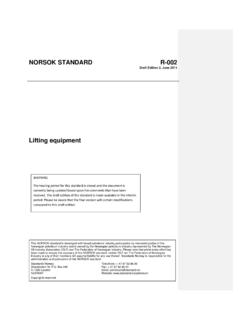
4 The following procedures may be used to completely disassemble and reassemble the 217, and 227 Series Torque Generators. It is recommended that the torque generator be thoroughly cleaned before any repairs are attempted. When cleaning, be sure all open ports are sealed. Although not all drawings show the torque generator in a vise or on a bench, we recommend that you follow instructions in the steps as to the placement of parts whether it be in a vice or on the bench. 5. Power Steering 217 Series and 227 Series Torque Generators Vise Jaws Output Shaft (top View) (power end) Up Quad Seal Housing (Standard). Washer 1 To disassemble the torque generator, first support the unit Washer in a vertical position with the seven cap screws up and control end shaft down.
5 Shaft and Retaining Ring (power end). IMPORTANT: When a bench vise is used to support the torque generator, do not to use excessive clamping pressure Housing (bearings needle type). on the control housing. Excessive pressure can distort the housing. When using a vise, CLAMP ACROSS PORT FACE. 5 Remove both washers from the housing (power end), and SIDES ONLY. reposition the housing with seal end up. Use small screwdriver or similar tool to remove quad seal from the housing. Housing 2 With the torque generator firmly supported, use a six-point with two bearing sets (needle type) use the same output shaft, drive (E10) socket wrench and remove seven cap screws (early quad seal, washers, and retaining ring as the standard housing.)
6 Production units used 12 point drive screws). However, if bearings are to be replaced they are not sold separately as replacement parts. Cap Screw Gerotor or Geroler OUT. OUT. AUX. AUX Drive IN Key IN. (power end). Housing and Shaft Assembly Spacer Plate O-ring 3 Remove the housing (power end) and shaft assembly. 6 Use a small screwdriver or similar tool to remove o-ring from the spacer plate. 4 Turn the housing and shaft assembly over and remove the shaft with retaining ring in place. 7 Remove spacer plate from the gerotor or Geroler. NOTE: In most cases it is not necessary to remove the 8 Remove drive (power end) from the gerotor or Geroler. retaining ring from the shaft. 9 Remove o-ring from the gerotor or Geroler.
7 6. Power Steering 217 Series and 227 Series Torque Generators O-ring Drive Spacer Spacer Geroler Valve Housing Washer Plate Valve Housing . OUT. 227 Series AUX. IN. OUT. AUX. IN Sleeve O-ring Shaft Seal Spool (can be Centering Springs Gerotor Quad Seal Retaining Ring or Lip Seal) and Cross Pin Drive 16 Reposition valve housing, shaft horizontal and remove the spool/sleeve assembly. OUT. AUX. IN. 17 Reposition valve housing shaft end up. Use a small O-ring screwdriver or similar tool to remove shaft seal. Spacer Plate 18 Remove the washer from spool/sleeve assembly. O-ring Valve Housing 217 Series 6 Springs Sleeve (Standard). NOTE: Remove the gerotor or Geroler, try to keep all parts together, Geroler has 7 rolls to retain along with the star Pin (step 10).
8 10 Remove the gerotor or Geroler. Spool and Retaining Ring 11 Remove the spacer (217 Series will not have this spacer). 12 Using a small screwdriver or similar tool, remove the o-ring 6 Springs and 4 Spacers from the spacer plate. for Increased Input Torque Spool (Special for Increased Input Torque). 13 Remove spacer plate from the valve housing. 14 Again using a small screwdriver or similar tool, remove 19 To separate spool from the sleeve, the cross pin must be o-ring from the valve housing. removed. To remove the cross pin, use a small screwdriver or similar tool and push pin from the spool/sleeve. 15 Remove the control end drive from the spool/sleeve assembly in the valve housing. 20 With cross pin removed, push spool forward to disengage the control spool and centering springs from the sleeve.
9 NOTE: To prevent possible loss of the (six) centering springs, cover the control spool and springs with a clean shop towel when pushing springs from the spool. This will help contain springs in one location (step 21). 21 Remove centering springs from the control spool (and if applicable, four spring spacers). Retaining ring on spool need not be removed if no damage is apparent. 7. Power Steering 217 Series and 227 Series Torque Generators Plug O-ring Relief Valve Valve Housing Spring InstallationTool Alternate Method OUT. (for Relief AUX. IN Valve Option) Add One Springs Spring at a Time NOTE: Valve housing with inlet relief valve has one o-ring on 23 In preparation of installing the control spool and sleeve the plug.
10 After o-ring replacement, install relief valve and centering spring set, stand all springs on a clean flat surface plug into valve housing and torque plug to 41-46 Nm with the notched side of the centering spring pointed down. [30-34 lb-ft]. Next, place centering springs with arched side of each set of three pointing toward each other as shown above. Reassembly Procedures 24 To install centering springs, first insert spring installation Replace all worn and damaged parts, also a good service policy tool through spring openings in the spool/sleeve. Insert one is to replace all seals. Lubricate all seals with petroleum jelly, end of the entire centering spring set (with notched side toward and also lubricate all mating surfaces with good clean hydraulic the spool/sleeve) into the spring installation tool.