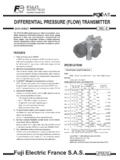
Transcription of Series 607 Differential Pressure Transmitter
1 SPECIFICATIONSGENERALM aximum Pressure :10 psig ( bar).Media Compatibility: Air and non-conductive, non-corrosive Supply: 12-36 VDC, Signal: 4-20 mA DC, two Resistance: 0-1045 ohms Vmin. = 12V + [(.022A)(RL)].Warm-up Time:15 seconds. PERFORMANCE AT 70 at zero: 4 at full span:20 : of full Time: 250 LIMITSO perating: -20 to 160 F (-29 to 71 C), 10-95% RH, : 35 to 135 F (2 to 57 C).Storage: -40 to 180 F (-40 to 82 F).Thermal Effects: F (zero and span).MECHANICALH ousing: 300 Series stainless steel (NEMA 2). Pressure Connections: 4 barbed stainless steel for 3/16 ID : lb (472 g).Span and Zero: Factory set to specified range.
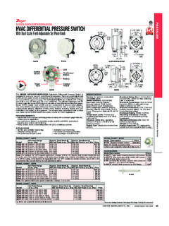
2 Externally accessible, non-interactive, 10% Dwyer Series 607 Differential Pressure Transmitter converts positive,negative (vacuum) or Differential pressures of clean, dry air or other non-conductive, non-corrosive gases into a standard two wire, 4-20 mA output factory calibrated models are available with ranges from to 0-25 All models employ a variable capacitance transducer with a micro-machined, ultra thin silicon diaphragm enabling precision measurement andcontrol of very low pressures. Because no epoxies or other organics are used toseal the sensor, performance is exceptionally stable and drift free.
3 It is also highlyresistant to overpressure, shock and vibration. See specifications for 607 Transmitter Models & RangesSeries 607 Differential Pressure TransmitterSpecifications - Installation and Operating InstructionsBulletin E-76 Model607-0607-1607-2607-3607-4607-7607-8 Range in of Full Scale*Model607-9607-0B607-1B607-2B607-3B 607-4B607-7 BRange in in of Full Scale*Model607-21607-71 Range in *Includes Linearity, Hysteresis, and RepeatabilityDWYER INSTRUMENTS, INC. Phone: 219/879-8000 BOX 373 MICHIGAN CITY, IN 46360, Fax: 219/872-9057e-mail: [ ]3-59/64 [ ]4-9/16 [ ]1-21/32[ ]7/32 [ ]3-13/32[ ]3-7/8[ ]4-3/8[ ] 1-53/64 [ ]1-19/64 [ ] Copyright 2013 Dwyer Instruments, in 5/13FR# 01-440685-00 Rev.
4 1 DWYER INSTRUMENTS, INC. Phone: 219/879-8000 BOX 373 MICHIGAN CITY, IN 46360, Fax: 219/872-9057e-mail: Location: Select a clean, dry location free of excess vibration where thetemperature of the unit with be between -20 and 160 F. Distance from thereceiver is limited only by total loop resistance. See Electrical Connections . Thetubing supplying Pressure to the Transmitter can be run practically any tubing lengths will not affect accuracy but response time will be Position: The Series 607 Transmitter is not position sensitive. However, it isrecommended that you avoid mounting with Pressure connections pointing upbecause of the chance of condensed moisture entering the interior.
5 Moisture canalso be avoided by routing tubing with a low point just ahead of the Mounting: Attach to mounting surface with two #8 or #10 screws in themounting slots Pressure connections: The Series 607 Transmitter is shipped with a shortlength of tubing installed between the ports to keep the interior clean. Remove itand discard after unit is mounted. Connect positive (above atmospheric) pressureto port marked HIGH and vent the LOW port. Connect negative (vacuum) Pressure to port marked LOW and vent the HIGH port. For differentialpressures, connect the higher one to the HIGH port and the lower one to the LOW port.
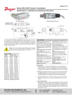
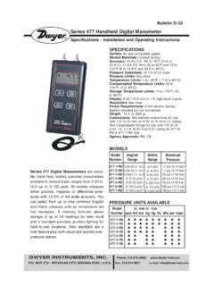
6 ELECTRICAL CONNECTIONC aution: Do not exceed the specified supply voltage rating. Permanent damage,not covered by warranty, may result. This unit is not designed for AC voltageoperation. Electrical connections to the Series 607 Transmitter are made to the two screwson the terminal strip labeled + and -. If polarity is inadvertently reversed, the loopwill not function properly but no damage will be done to the Transmitter becauseof internal circuit protection. An external power supply delivering 12 to 36 VDCmust be used to power the control loop in which the Transmitter is to Figure B for connection of the power supply, Transmitter and power required to generate the 4-20 mA output signal depends on the loopresistance of the circuit and is proportional to the resistance according to thegraph and formula in Figure C.
7 The maximum length that can be used in thecurrent loop is a function of wire size and receiver resistance. A shielded twoconductor cable is recommended for control loop wiring. Make sure the total loopresistance is within the operating region as shown in Figure Series 607 Transmitter is factory calibrated to the range listed in the modelnumber chart. Range is defined as that Pressure which when applied to thetransmitter will produce a 20 milliamp current in the loop. Zero Pressure willproduce 4 milliamps. If fine adjustment of calibration is required, used thefollowing procedure:1).
8 With the Transmitter connected to its companion receiver, insert amilliammeter in Series with the current loop. A controllable Pressure source shouldbe teed to the high Pressure port of the Transmitter and to an accurate pressuregage or ). Apply electrical power to the system and allow 15 seconds form componentsto ). With no Pressure applied to the Transmitter remove blowout disc and adjust zero control so loop current is 4 ). Apply full span Pressure and adjust loop current to 20 mA using span ). Remove the milliammeter from the circuit, replace blowout disc, and placesystem in final installation of the Series 607 Differential Pressure Transmitter , noroutine maintenance is required.
9 A periodic check of system calibration isrecommended. These devices are not field repairable and should be returned tothe factory if recalibration or other service is required. After first obtaining aReturned Goods Authorization (RGA) number, send the material, freight prepaid,to the following address. Please include a clear description of the problem plusany application information Instruments, : Repair Department102 Highway 212 Michigan City, IN : RECEIVER MAY BE IN Series WITH + or - LEG OF CONTROL LOOPPOWERSUPPLY12-36 VDCSEE FIG. CRECEIVER (RL)GROUNDOPTIONALSERIES 607 PRESSURETRANS-MITTER+-+-Figure B110010009008007006005004003002001000 LOOP RESISTANCE ( )OPERATING RANGEVMIN = 12V + (.)
10 022A x RL)MAXIMUM VALUE (1090)0 5 10 12 20 25 30 36 40 POWER SUPPLY VOLTAGE - VDCF igure C