Transcription of Series DTFF Variable-Area Flowmeter for Low Flow Rates
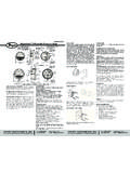
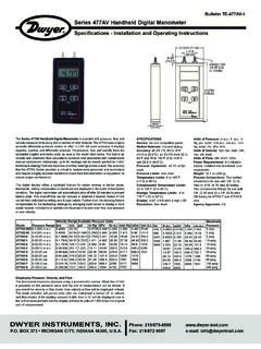
1 Series dtff Variable-Area Flowmeter for Low Flow RatesSpecifications - Installation and Operating InstructionsBulletin F-DTFFDWYER INSTRUMENTS, INC. Phone: 219 BOX 373 MICHIGAN CITY, INDIANA 46360, Fax: 219/872-9057e-mail: Compatible gases & liquids & oils. Wetted Materials: Body: 316 SS;Spring: 302 SS;Range spring: 302 SS;Magnet: PTFE-coated;Orifice piston: Acetal;Diaphragm: Limit: -22 to 200 F (-30 to 93 C).Pressure Limit: 3000 psig (200 bar).Accuracy: Liquid/oil calibration: 2% FS; Air calibration: 5% : 1% : Diameter dial face ( mm). Process Connections: 1/4 female : 4 lb ( kg).The Series dtff Fixed-Orifice Flowmeter for Low Flow Ratesmeasures water, oil, or air flow Rates with great accuracy at anaffordable price. Rugged stainless steel construction ensures greatcompatibility and is an excellent choice for high line pressureapplications, with a maximum pressure of 3000 psig (200 bar).
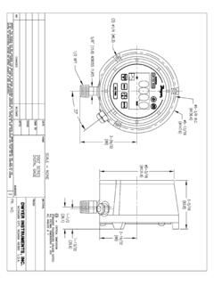
2 This is allwithout sacrificing the sensitivity required for low flow a wide variety of flow ranges available, the Series dtff can beused with many different applications all at an economical Series dtff Fixed-Orifice Flowmeter for Low Flow Rates arecalibrated at the factory for mounting in the horizontal position andshould be installed that way for maximum accuracy. The unit will normally retain its accuracy tolerance for the useful life ofthe device. If you want to check the accuracy, do so only withinstruments of certified accuracy. Do not attempt to check accuracy withother flowmeters piped in Series . Even minor variations in piping andback pressure can cause significant differences in indication. If in doubt,return the Flowmeter to the factory for a calibration check. 1-1/2[ ]3/4[ ]11/16[ ]2[ ]1-1/2[ ]1/4 NPTINLET & OUTLET1-31/64[ ]1-7/8[ ]2-11/32[ ]1/4 NPT PROCESS CONNECTION 2-59/64[ ]1[ ]CalibrationWaterWaterWaterWaterWaterWat erWaterWaterWaterOilOilOilOilOilOilOilOi lOilAirModelDTFF-1S-2 WDTFF-1S-4 WDTFF-1S-5 WDTFF-1S-8 WDTFF-1S-10 WDTFF-1S-15 WDTFF-1S-20 WDTFF-1S-25 WDTFF-1S-40 WDTFF-1S-2 ODTFF-1S-4 ODTFF-1S-5 ODTFF-1S-8 ODTFF-1S-10 ODTFF-1S-15 ODTFF-1S-20 ODTFF-1S-25 ODTFF-1S-40 ODTFF-1S-5 ARange0 to 2 GPH0 to 4 GPH0 to 5 GPH0 to 8 GPH0 to 10 GPH0 to 15 GPH0 to 20 GPH0 to 25 GPH0 to 40 GPH0 to 2 GPH0 to 4 GPH0 to 5 GPH0 to 8 GPH0 to 10 GPH0 to 15 GPH0 to 20 GPH0 to 25 GPH0 to 40 to 5 SCFMF-DTFF_SSS-1000 4/4/12 9:44 AM Page 1 LocationSelect a location where the Flowmeter can be easily read and where thetemperature will not exceed 200 F (93 C).
3 The mounting surface andpiping to the Flowmeter should be free from excessive vibration. If pulsingflow or vibration causes excessive pointer oscillation, contact factory forways to provide additional dampening. Because the device operates through a magnetic coupling system,magnetic material near the flow block can affect accuracy. To minimize theeffect of outside interference, keep magnetic materials at least 3 inches( cm) away from the unit. Inlet PipingIt is a good practice to have the inlet port of the Flowmeter be as free ofelbows, restrictions and size changes as possible. Inlet piping should be asclose to the Flowmeter connection size as possible to avoid possibleturbulence, which can occur with drastic size changes. The length of theinlet piping has very little effect on normal pressure fed flowmeters. For vacuum service, the inlet piping should be as short and open aspossible to allow operation at or near atmosphere pressure, thusmaintaining the accuracy of the device.
4 Note that for vacuum service, anyflow control valve must be installed on the discharge side of the Flowmeter . Outlet PipingPiping on the outlet port should be at least as large as the flowmeterconnection. For flowmeters fed by air or gas pressure, the piping should beas large and short as possible. This is so pressure within the device will beat or near atmosphereic for maximum accuracy. This is less important forwater or liquid flowmeters since the flowing media is generally notcompressible, and therefore back pressure will not affect the calibration ofthe instrument. OperationIf the media is likely to be dirty, it is recommended that a 50 micron filter isplaced upstream of the inlet port to assure a clean fluid medium flowsthrough the Flowmeter . After all connections are complete, introduce flow asslowly as possible to avoid damage. With liquid flow, it may be necessaryto purge air from the system before readings stabilize.
5 No lubrication orperiodic servicing is required. Keep case exterior, including front cover,clean for best visibility. MAINTENANCE/REPAIRUpon final installation of the Series dtff , no routine maintenance isrequired. The Series dtff is not field serviceable and should be returnedif repair is needed. Field repair should not be attempted and may to Terms and Conditions of Sales in our catalog and on our customer service to receive a Return Goods Authorization numberbefore shipping the product back for repair. Be sure to include a briefdescription of the problem plus any additional application INSTRUMENTS, INC. Phone: 219 BOX 373 MICHIGAN CITY, INDIANA 46360, Fax: 219/872-9057e-mail: Copyright 2012 Dwyer Instruments, in 4/12FR# R4-443967-00 Rev. 2F-DTFF_SSS-1000 4/4/12 9:44 AM Page 2