Transcription of Series TM2 Digital Rate Meter & Totalizer - Dwyer Instruments
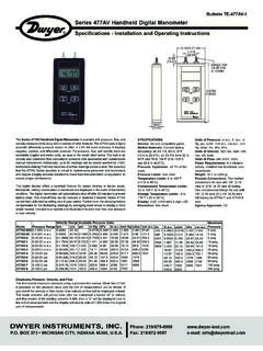
1 Series TM2 Digital Rate Meter & TotalizerSpecifications - Installation and Operating InstructionsBulletin F-41-TM2 Dwyer Instruments , INC. Phone: 219 BOX 373 MICHIGAN CITY, INDIANA 46361, Fax: 219/872-9057e-mail: flow rate or total flowwith Model TM2 Flow features a four digit flow rate display and an eight digit total-izing display with a programmable, five position decimal toggle between rate and total with front-panel scaling factor to define flow rate in engineering units such asmL/min, L/min, or I. UNPACKING YOUR DISPLAYC hecking for external damage to shipmentYour Model TM2 Display was packed by the manufacturer insuch a way that you should receive it with no damage. If externaldamage is noted upon receipt of the package, please contact theshipping company (not Dwyer Instrument, Inc.) Instruments , Inc. will not be liable for damage to themeter once it has left the manufacturing the displayAfter external inspection of the product, proceed to open thepackage from the top, taking care not to cut too deep.
2 Removeall documentation (if any) resting on top of the packing all products for concealed shipping damage. If damageis noted, please contact the shipping carrier and/or DwyerInstruments, Inc. to resolve the unpacking the products from the shipment, please takecare to remove all products from the box. check thoroughly forextra cables, power adapters, and other options listed on thepacking slip, if against damaging the unitAny damage inflicted on the display by the customer will not berepaired under warranty by Dwyer Instruments , Inc. See Section6 for more VDC max. pulse. Accuracy: Input Impedance:27 k at 3 VDC. Totalizer Type: UP count. Rate Indication Type:Frequency. Count Input Speed:10 kHz @ 50% duty cycle. Totalizing to with five positiondecimal point. Rate Indication Range: to 9999 (five position decimalpoint).
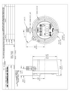
3 Update :8-digit LCD, 7/16" Limits:32 to 131 F (0 to 55 C).Housing Material:Cycolac :One 3V lithium battery (included).Average Battery Life:Approximately 5 :1 Ib ( kg).Agency [ ]2-31/32[ ]1-37/64[ ]1-1/8[ ]F-41-TM2:Model PHO-1 8/24/10 11:51 AM Page 1 Section II. INSTALLING YOUR MODEL TM2 Mounting the displayWhen choosing a place to mount the display, keep these threethings in mind: a. The display should not be mounted near a solenoid orother inductive Enough ventilation should be supplied to keep the Totalizer operating within the temperature specifications (see Selection 5).c. This display should not be mounted in a heavy vibration recommended mount for the Model TM2 display is panel-mount. The recommended panel cutout for the display is wide (68 mm) by tall (33 mm).To install the unit in a panel, first remove the two fastenerslocated on the side of the unit.
4 These slide tightly in grooves andshould slide out without too much trouble. DO NOT MISPLACETHESE FASTENERS!!!With the fasteners removed, the display should slide into thepanel cutout. The included gasket should be between the paneland the face of the display. Making sure the gasket is properlyaligned and not twisted, slide the display in place. Reinstall thefasteners by sliding them in their grooves until they stop. Thescrews on the fasteners should be facing the panel and the headof the screw facing away from the the set screws of the fasteners using a flatheadscrewdriver in a clockwise motion. They should be equallytightened until the display is snug and the gasket is mounted with the provided fasteners, gasket, and specificrectangular panel cutout, the Model TM2 display achieves aNEMA-4X connections to the displayThe Model TM2 is self-powered using an internal lithium battery,thus there is no need for external power.
5 The typical life of thisbattery is 5 connections are made, power the display by removing thetemporary insulator on the back of the unit. Simply pull the whitetab out -- there is no need to open the battery #1: This pin should be connected to the ground of the pulse signal. In most cases, this will be the same as the ground of the Flo-Sensor that the Model TM2 Display is connected #2: This pin is not used with any Dwyer Instruments , Inc. #3: This is the pulse signal input. The Model TM2 accepts all TF10xx Series Flo-Sensor pulse outputs. These are peak squarewave pulses directly proportional to the flow #4: This pin is used for remote reset. When momentarily connected to ground, this pin will reset the Totalizer just like the front panel reset #5: This pin is used to enter program mode. When connected to the ground, the Model TM2 enters program mode, described in Section #6-Pin #8: These pins are not the last page for wiring diagrams of connections to variousFlo-Sensors and other RecommendationsFollowing these suggestions will increase noise immunity andlengthen unit life.
6 Cable: The connection between the count source and thetotalizer/ratemeter should be made with a two-conductorshielded cable. The shield should be connected to earth groundat one end only. The connecting cable should not be run inconduits with cables switching high inductive Coil Suppression: If a relay contact is used as a countsource, the relay coil should be suppressed. This can beaccomplished with an RC network for AC coils or a diode for : This Totalizer /ratemeter should not be mounted near asolenoid or other inductive devices. Enough ventilation shouldbe supplied to keep the Totalizer operating within the temperaturespecifications. Do not mount this unit in a heavy vibration #1 Signal &Reset GroundPin #2 Not UsedPin #3 Signal In(Pulse Input)Pin #4 RemoteReset(optional)Pin #5 EnableProgramModeF-41-TM2:Model PHO-1 8/24/10 11:51 AM Page 2 Section III.
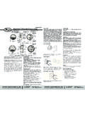
7 PROGRAMMING THE TM2 The Dwyer Instruments , Inc. Model TM2 Display is a versatilemeter that will indicate flow rates and totalize flow in virtually anyunit of measurement. To do this, it uses 2 numerical factors(programmed by the user) to customize and match each displaywith each particular successfully program this display, you must first understandhow it works and what you are programming into it. Programmode uses six different screens to program rate and total are used as follows: Totalizer FUNCTION:Screen #1: The Significant digits of the Totalizer Multiplierare entered here. The Model TM2 uses theseto calculate total #2: This screen is simply a decimal placer. Since only the significant digits of the Totalizer Multiplier are entered in screen #1, this allowsyou to make up for the insignificant zeros not entered FUNCTION:Screen #3: The significant digits of the Rate Multiplier areentered here.
8 The Model TM2 uses these to calculate current rate of #4: This screen is another decimal placer. Since only the significant digits of the Rate Multiplierare entered in screen #3, this allows you to make up for the insignificant zeros not :Screen #5: This screen should always read 1 . It is not used with any Model TF10xx #6: This screen enables/disables the front panel reset understand the insignificant/significant digit importance, youmust understand that many of your Rate and Totalizer Multiplierswill be very small, with several zeros in front of them, such However, screens 1 and 3, where those numbers areentered, will only allow 6 to 4 digits, respectively. There is,therefore, no room for those preceding zeros. For each zeroremoved, the decimal place in the following screen shifts oneleft. This is further described in Section 3.
9 Program ModeIn order to program the factors into the display, it must first be putinto program mode (of course, the unit must be powered, seeSection ). To do this, simply connect the ground input (pin #1)to the enable program input (pin #5) with a short wire, jumper, oralligator chip. Make sure the connection will hold well enough foryou to program a Series of numbers into the unit. When you arefinished and wish to exit program mode, simply remove the Model TM2 operates on pulse inputs, the pulse output(frequency) of the Flo-Sensor at 100% flow must be number is located in one of three places:1. On a tag attached to a fitting of the Flo-Sensor2. On a calibration data sheet, included with theFlo-Sensor3. On a label near the connector of the Flo-Sensor The label should provide pulse output (PPS) information of theparticular Flo-Sensor at the rated 100% flow of the example, for a Model TF1032 Flo-Sensor, rated from L/min, you would need the pulse output data of that Flo-Sensor at L/min.
10 (The pulse output is usually given when thevoltage output is VDC, or 100% flow.)Note:If the tag listing the pulse rate is missing, please contactDwyer Instruments , Inc. for pulse output information on thatparticular Flo-Sensor. Please provide the model number, serialnumber, and flow range of the Flo-Sensor you are requestinginformation on. It is also possible to determine the pulse outputfrequency by using a volt Meter and the Model TM2 methods of programming described in Section , setscreen #3 to read and screen #4 to read 0000 . Hookthe volt Meter up to the analog voltage output of the the voltage output as a guide, provide enough flowthrough the sensor to wear the sensor outputs VDC. Placethe TM2 in rate mode and the number displayed will be the pulseoutput of the sensor at 100% rated the Rate MultiplerThe Rate Multiplier is the number that the Model TM2 uses tointerpret pulses into rate.