Transcription of Si4730/31/34/35-D60 Data Sheet - Silicon Labs
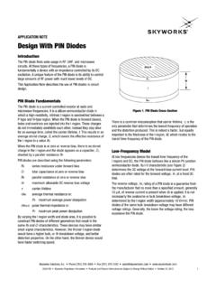
1 Skyworks Solutions, Inc. Phone [781] 376-3000 Fax [781] 376-3100 Skyworks Proprietary Information Products and Product Information are Subject to Change Without Notice November 10, 2021Si4730/31/34/35-D60 BROADCAST AM/FM/SW/LW RADIO RECEIVERF eaturesApplicationsDescriptionThe Si473x-D60 digital CMOS AM/FM radio receiver IC integrates the completebroadcast tuner and receiver function from antenna input to digital audio device leverages the Skyworks broadcast proven digital low-IF architecture,enabling a cost-effective, digital audio platform for consumer electronicapplications with high TDMA noise immunity, superior radio performance, andhigh fidelity audio power Block Diagram Worldwide FM band support (64 108 MHz) Worldwide AM band support (520 1710 kHz)
2 SW band support (Si4734/35)( MHz) LW band support (Si4734/35)(153 279 kHz) Excellent real-world performance Integrated VCO Advanced AM/FM seek tuning Automatic frequency control (AFC) Automatic gain control (AGC) Digital FM stereo decoder Programmable de-emphasis Advanced Audio Processing Seven selectable AM channel filters AM/FM/SW/LW digital tuning EN55020 compliant No manual alignment necessary Programmable reference clock Adjustable soft mute control RDS/RBDS processor (Si4731/35) Digital audio out 2-wire and 3-wire control interface Integrated LDO regulator Wide range of ferrite loop sticks and air loop antennas supported QFN and SSOP packages RoHS compliant Table and portable radios Mini/micro systems CD/DVD and Blu-ray players Stereo boom boxes Modules for consumer electronics Clock radios Mini HiFi and docking stations Entertainment systemsADCSi473x-D60 ~ V (QFN) ~ V (SSOP)RDS(Si4731/35) - VSENCONTROLINTERFA CESCLKLNAAGCLNAAGCGNDADCMuxMuxDACLOW-IFS DIORSTDIGITALAUDIODFSDOUTRCLKAM / LWANTRFGNDFMIFM / SW ANT+This product, its features, and/or itsarchitecture is covered by one or more ofthe following patents, as well as otherpatents, pending and issued, bothforeign and domestic: 7,127,217;7,272,373; 7,272,375.
3 7,321,324;7,355,476; 7,426,376; 7,471,940;7,339,503; 7,339, Information:See page AssignmentsSi473x-D60(SSOP)Si473x-D60 (QFN)GNDPAD12317181920111213146789451610 15 GPO2/[INT]VDDOUTLOUT/[DFS]ROUT/[DOUT]GND RSTNCAMIRCLKSDIOVAFMIRFGNDGPO3/[DCLK]NCG PO1 DFSSCLKSENLOUT/[DFS]ROUT/[DOUT]DBYPVDGPO 2/[INT]GPO3/[DCLK]DOUTDFS123456789101112 GPO1 VASDIONCNCRCLKSENFMIRFGNDSCLKGNDNCNCRSTG NDAMI242322212019181716151413Si4730/31/3 4/35-D602 Skyworks Solutions, Inc. Phone [781] 376-3000 Fax [781] 376-3100 Skyworks Proprietary Information Products and Product Information are Subject to Change Without Notice November 10, 2021 TABLE OF CONTENTSS ectionPage1. Electrical Specifications .. 42. Typical Application Schematic .. QFN Typical Application Schematic .. SSOP Typical Application Schematic.
4 183. Bill of Materials .. QFN/SSOP Bill of Materials .. 194. Functional Description .. Overview .. Operating Modes .. FM Receiver .. AM Receiver .. SW Receiver .. LW Receiver .. Digital Audio Interface .. Stereo Audio Processing .. Received Signal Qualifiers .. Volume Control .. Stereo DAC .. Soft Mute .. FM Hi-Cut Control .. De-emphasis .. RDS/RBDS Processor (Si4731/35 Only) .. Tuning .. Seek .. Reference Clock .. Control Interface .. GPO Outputs .. Firmware Upgrades .. Reset, Powerup, and Powerdown .. 2 V Operation (SSOP Only) .. Programming with Commands .. 275. Pin Descriptions .. Si473x-D60-GM .. Si473x-D60-GU .. 296. Ordering Guide .. 307. Package Outline .. Si473x-D60 QFN .. Si473x-D60 SSOP .. 328. PCB Land Pattern.
5 Si473x-D60 QFN .. Si473x-D60 SSOP .. 35Si4730/31/34/35-D60 Skyworks Solutions, Inc. Phone [781] 376-3000 Fax [781] 376-3100 Skyworks Proprietary Information Products and Product Information are Subject to Change Without Notice November 10, 20219. Top Markings .. Si473x-D60 Top Marking (QFN) .. Top Marking Explanation (QFN) .. Si473x-D60 Top Marking (SSOP) .. Top Marking Explanation (SSOP) .. 3710. Additional Reference Resources .. 38 Document Change List ..39 Contact Information .. 40Si4730/31/34/35-D604 Skyworks Solutions, Inc. Phone [781] 376-3000 Fax [781] 376-3100 Skyworks Proprietary Information Products and Product Information are Subject to Change Without Notice November 10, 20211. Electrical SpecificationsTable 1. Recommended Operating Conditions1 ParameterSymbolTest ConditionMinTypMaxUnitAnalog Supply VDigital and I/O Supply Supply Powerup Rise TimeVDDRISE10 sInterface Power Supply Powerup Rise TimeVIORISE10 sAmbient TemperatureTA 202585 minimum and maximum specifications apply across the recommended operating conditions.
6 Typical values apply at VA= V and 25 C unless otherwise stated. 2. SSOP devices operate down to 2 V at 25 C. See section 2 V Operation (SSOP Only) for Solutions, Inc. Phone [781] 376-3000 Fax [781] 376-3100 Skyworks Proprietary Information Products and Product Information are Subject to Change Without Notice November 10, 2021 Table 2. DC Characteristics (VA= to V, VD= to V, TA= 20 to 85 C)ParameterSymbolTest ConditionMinTypMaxUnitFM ModeVAQFN Supply CurrentIFMVAD igital Output Mode1 Supply CurrentIFMVD Supply CurrentIFMVA Supply CurrentIFMVD Supply CurrentIFMVAA nalog Output Mode2 Supply CurrentIFMVD Supply CurrentIFMVA Supply ModeVAQFN Supply CurrentIAMVAD igital Output Mode Supply CurrentIAMVD Supply CurrentIAMVA Supply CurrentIAMVD Supply CurrentIAMVAA nalog Output Mode Supply CurrentIAMVD Supply CurrentIAMVA Supply CurrentIAMVD Powerdown CurrentIAPD 415 AVASSOP Powerdown Current Powerdown CurrentIDPDSCLK, RCLK inactive 310 AVDSSOP Powerdown CurrentSCLK, RCLK inactive 310 High Level Input x VD VD+ Level Input Voltage3 VIL x VDVHigh Level Input Current3 IIHVIN=VD= 10 10 ALow Level Input Current3 IILVIN=0V.
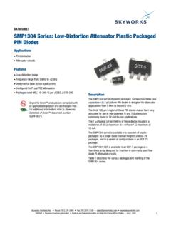
7 VD= 10 10 AHigh Level Output Voltage4 VOHIOUT= 500 x VD VLow Level Output Voltage4 VOLIOUT= 500 A x by Backwards compatible mode to rev B and rev C. Additional features on this device may increase typical supply For input pins SCLK, SEN, SDIO, RST, RCLK, DCLK, DFS, GPO1, GPO2, and For output pins SDIO, DOUT, GPO1, GPO2, and Solutions, Inc. Phone [781] 376-3000 Fax [781] 376-3100 Skyworks Proprietary Information Products and Product Information are Subject to Change Without Notice November 10, 2021 Figure 1. Reset Timing Parameters for Busmode SelectTable 3. Reset Timing Characteristics1,2,3(VA= to V, VD= to V, TA= 20 to 85 C)ParameterSymbolMinTypMaxUnitRST Pulse Width and GPO1, GPO2/INT Setup to RST tSRST100 sGPO1, GPO2/INT Hold from RST tHRST30 nsRST Pulse Release time before VDD/VIO turn offtRRST30 nsImportant selecting 2-wire mode, the user must ensure that a 2-wire start condition (falling edge of SDIO while SCLK is high) does not occur within 300 ns before the rising edge of When selecting 2-wire mode, the user must ensure that SCLK is high during the rising edge of RST, and stays high until after the first start When selecting 3-wire mode, the user must ensure that a rising edge of SCLK does not occur within 300 ns before the rising edge of If GPO1 and GPO2 are actively driven by the user, then minimum tSRST is only 30 ns.
8 If GPO1 or GPO2 is hi-Z, then minimum tSRST is 100 s, to provide time for on- chip 1 M devices (active while RST is low) to pull GPO1 high and GPO2 RST must be held low for at least 100 s after all voltage supplies have been ramped RST needs to be asserted (pulled low) prior to any supply voltage being ramped Solutions, Inc. Phone [781] 376-3000 Fax [781] 376-3100 Skyworks Proprietary Information Products and Product Information are Subject to Change Without Notice November 10, 2021 Table 4. 2-Wire Control Interface Characteristics1,2,3(VA= to V, VD= to V, TA= 20 to 85 C)ParameterSymbolTest ConditionMinTypMaxUnitSCLK FrequencyfSCL0 400kHzSCLK Low sSCLK High sSCLK Input to SDIO Setup (START) sSCLK Input to SDIO Hold (START) sSDIO Input to SCLK SetuptSU:DAT100 nsSDIO Input to SCLK Hold4,5tHD:DAT0 900nsSCLK input to SDIO Setup (STOP) sSTOP to START sSDIO Output Fall Timetf:OUT 250nsSDIO Input, SCLK Rise/Fall Timetf:INtr.
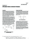
9 IN 300nsSCLK, SDIO Capacitive LoadingCb 50pFInput Filter Pulse SuppressiontSP 50 VD= 0 V, SCLK and SDIO are low When selecting 2-wire mode, the user must ensure that a 2-wire start condition (falling edge of SDIO while SCLK is high) does not occur within 300 ns before the rising edge of When selecting 2-wire mode, the user must ensure that SCLK is high during the rising edge of RST, and stays high until after the first start condition. 4. The Si473x-D60 delays SDIO by a minimum of 300 ns from the VIH threshold of SCLK to comply with the minimum tHD:DAT The maximum tHD:DAT has only to be met when fSCL= 400 kHz. At frequencies below 400 KHz, tHD:DAT may be violated as long as all other timing parameters are +20 +Si4730/31/34/35-D608 Skyworks Solutions, Inc. Phone [781] 376-3000 Fax [781] 376-3100 Skyworks Proprietary Information Products and Product Information are Subject to Change Without Notice November 10, 2021 Figure 2.
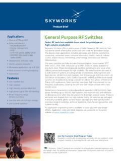
10 2-Wire Control Interface Read and Write Timing ParametersFigure 3. 2-Wire Control Interface Read and Write Timing DiagramSCLK70%30%SDIO70%30%STARTSTARTSTO Ptf:INtr:INtLOWtHIGHtHD:STAtSU:STAtSU:ST OtSPtBUFtSU:DATtr:INtHD:DATtf:IN, tf:OUTSCLKSDIOSTARTSTOPADDRESS + R/WACKDATAACKDATAACKA6-A0, R/WD7-D0D7-D0Si4730/31/34/35-D60 Skyworks Solutions, Inc. Phone [781] 376-3000 Fax [781] 376-3100 Skyworks Proprietary Information Products and Product Information are Subject to Change Without Notice November 10, 2021 Figure 4. 3-Wire Control Interface Write Timing ParametersFigure 5. 3-Wire Control Interface Read Timing ParametersTable 5. 3-Wire Control Interface Characteristics(VA= to V, VD= to V, TA= 20 to 85 C)ParameterSymbolTest ConditionMinTypMaxUnitSCLK FrequencyfCLK0 High TimetHIGH25 nsSCLK Low TimetLOW25 nsSDIO Input, SEN to SCLK SetuptS20 nsSDIO Input to SCLK HoldtHSDIO10 nsSEN Input to SCLK HoldtHSEN10 nsSCLK to SDIO Output ValidtCDVRead2 25nsSCLK to SDIO Output High ZtCDZRead2 25nsSCLK, SEN, SDIO, Rise/Fall timetR, tF 10nsNote:When selecting 3-wire mode, the user must ensure that a rising edge of SCLK does not occur within 300 ns before the rising edge of ,R/W,A4-A1 Address InData InD15D14-D1D0tHIGHtLOWtRtF Cycle Bus TurnaroundSCLK70%30%SEN70%30%SDIO70%30%t HSDIOtCDVtCDZA ddress InData OutA7A0A6-A5,R/W,A4-A1D15D14-D1D0tStStHS ENSi4730/31/34/35-D6010 Skyworks Solutions, Inc.