Transcription of Si861x-2x Data Sheet - Silicon Labs
1 Si861x/2x data SheetLow-Power Single and Dual-Channel digital IsolatorsSkyworks' family of ultra-low-power digital isolators are CMOS devices offering substan-tial data rate, propagation delay, power, size, reliability, and external BOM advantagesover legacy isolation technologies. The operating parameters of these products remainstable across wide temperature ranges and throughout device service life for ease ofdesign and highly uniform performance. All device versions have Schmitt trigger inputsfor high noise immunity and only require VDD bypass rates up to 150 Mbps are supported, and all devices achieve propagation delaysof less than 10 ns. Ordering options include a choice of isolation ratings ( , and5 kV) and a selectable fail-safe operating mode to control the default output state duringpower loss.
2 All products are safety certified by UL, CSA, VDE, and CQC, and productsin wide-body packages support reinforced insulation withstanding up to 5 Grade is available for certain part numbers. These products are built usingautomotive-specific flows at all steps in the manufacturing process to ensure the robust-ness and low defectivity required for automotive FEATURES High-speed operation DC to 150 Mbps No start-up initialization required Wide Operating Supply Voltage V Up to 5000 VRMS isolation Reinforced VDE 0884-10, 10 kV surge-capable (Si862xxT) 60-year life at rated working voltage High electromagnetic immunity Ultra low power (typical)5 V Operation mA per channel at 1 Mbps mA per channel at 100 V Operation mA per channel at 1 Mbps mA per channel at 100 Mbps Schmitt trigger inputs Selectable fail-safe mode Default high or low output (orderingoption) Precise timing (typical)
3 10 ns propagation delay ns pulse width distortion ns channel-channel skew 2 ns propagation delay skew 5 ns minimum pulse width Transient Immunity 50 kV/ s AEC-Q100 qualification Wide temperature range 40 to 125 C RoHS-compliant packages WB SOIC-16 SOIC-8 DFN-8 compact package Automotive-grade OPNs available AIAG compliant PPAP documentationsupport IMDS and CAMDS listing supportIndustrial Applications Industrial automation systems Medical electronics Isolated switch mode supplies Isolated ADC, DAC Motor control Power inverters Communications systemsSafety Regulatory Approvals UL 1577 recognized Up to 5000 VRMS for 1 minute CSA approval IEC 60950-1, 62368-1, 60601-1 (re-inforced insulation) VDE certification conformity Si862xxT options certified to re-inforced per VDE 0884-10 and62368-1 All other options certified toVDE 0884-10 (basic), 60950-1 (rein-forced), and 62368-1 (reinforced) CQC certification approval Applications On-board chargers Battery management systems Charging stations Traction inverters Hybrid Electric Vehicles Battery Electric VehiclesSkyworks Solutions, Inc.
4 Phone [781] 376-3000 Fax [781] 376-3100 Skyworks Proprietary Information Products and Product Information are Subject to Change Without Notice December 22, 202111. Ordering GuideIndustrial and Automotive Grade OPNsIndustrial-grade devices (part numbers having an -I in their suffix) are built using well-controlled, high-quality manufacturing flows toensure robustness and reliability. Qualifications are compliant with JEDEC, and defect reduction methodologies are used throughoutdefinition, design, evaluation, qualification, and mass production devices (part numbers having an -A in their suffix) are built using automotive-specific flows at all steps in themanufacturing process to ensure robustness and low defectivity.
5 These devices are supported with AIAG-compliant Production PartApproval Process (PPAP) documentation, and feature International Material data System (IMDS) and China Automotive MaterialData System (CAMDS) listing. Qualifications are compliant with AEC-Q100, and a zero-defect methodology is maintained throughoutdefinition, design, evaluation, qualification, and mass production Ordering Guide for Valid OPNs1, 2, 4 See the Top Marking section of this data Sheet for the part number Part Number(OPN)Automotive OPNs5, 6 Numberof InputsVDD1 SideNumberof InputsVDD2 SideMax DataRate(Mbps)DefaultOutputStateIsolatio nRating(kV) data Sheet Ordering GuideSkyworks Solutions, Inc. Phone [781] 376-3000 Fax [781] 376-3100 Skyworks Proprietary Information Products and Product Information are Subject to Change Without Notice December 22, 20212 Ordering Part Number(OPN)Automotive OPNs5, 6 Numberof InputsVDD1 SideNumberof InputsVDD2 SideMax DataRate(Mbps)DefaultOutputStateIsolatio nRating(kV) Options with Reinforced VDE 0884-10 Rating with 10 kV Surge SOIC-16 packages are RoHS-compliant with peak reflow temperatures of 260 C according to the JEDEC industry standard classifica-tions and peak solder Si and SI are used "R" at the end of the part number denotes tape and reel packaging temperature ranges is 40 to +125 devices (with an " A" suffix)
6 Are identical in construction materials, topside marking, and electrical parametersto their Industrial-Grade (with an " I" suffix) version counterparts. Automotive-Grade products are produced utilizing full automo-tive process flows and additional statistical process controls throughout the manufacturing flow. The Automotive-Grade partnumber is included on shipping the top markings of each device, the Manufacturing Code represented by either RTTTTT or TTTTTT contains as its firstcharacter a letter in the range N through Z to indicate Automotive-Grade. Si861x/2x data Sheet Ordering GuideSkyworks Solutions, Inc. Phone [781] 376-3000 Fax [781] 376-3100 Skyworks Proprietary Information Products and Product Information are Subject to Change Without Notice December 22, 20213 Table of Contents1.
7 Ordering System Theory of Eye Device Device Undervoltage Layout Supply Output Pin Fail-Safe Operating Typical Performance Electrical Pin Descriptions (WB SOIC-16)..286. Pin Descriptions (SOIC-8)..297. Pin Descriptions (DFN-8)..308. Package Outline: WB Land Pattern: WB Package Outline: Land Pattern: Package Outline: Land Pattern: Top Marking: WB Top Marking: Top Marking: Revision Solutions, Inc. Phone [781] 376-3000 Fax [781] 376-3100 Skyworks Proprietary Information Products and Product Information are Subject to Change Without Notice December 22, 202142. System Theory of OperationThe operation of an Si861x/2x channel is analogous to that of an opto coupler, except an RF carrier is modulated instead of light.
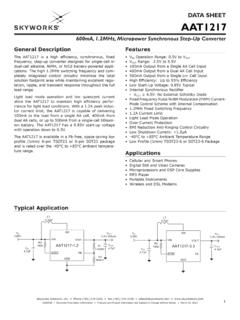
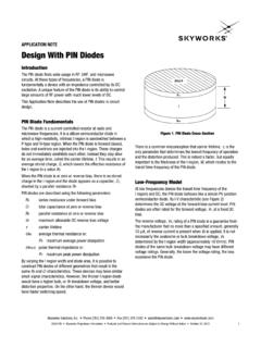
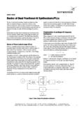
8 Thissimple architecture provides a robust isolated data path and requires no special considerations or initialization at start-up. A simplifiedblock diagram for a single Si861x/2x channel is shown in the figure Simplified Channel DiagramA channel consists of an RF Transmitter and RF Receiver separated by a semiconductor-based isolation barrier. Referring to thetransmitter, input A modulates the carrier provided by an RF oscillator using on/off keying. The Receiver contains a demodulator thatdecodes the input state according to its RF energy content and applies the result to output B via the output driver. This RF on/off keyingscheme is superior to pulse code schemes as it provides best-in-class noise immunity, low power consumption, and improved immunityto magnetic fields.
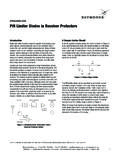
9 See the following figure for more Modulation SchemeSi861x/2x data Sheet System OverviewSkyworks Solutions, Inc. Phone [781] 376-3000 Fax [781] 376-3100 Skyworks Proprietary Information Products and Product Information are Subject to Change Without Notice December 22, Eye DiagramThe figure below illustrates an eye diagram taken on an Si8610. For the data source, the test used an Anritsu (MP1763C) Pulse PatternGenerator set to 1000 ns/div. The output of the generator's clock and data from an Si8610 were captured on an oscilloscope. Theresults illustrate that data integrity was maintained even at the high data rate of 150 Mbps. The results also show that 2 ns pulse widthdistortion and 350 ps peak jitter were Eye DiagramSi861x/2x data Sheet System OverviewSkyworks Solutions, Inc.
10 Phone [781] 376-3000 Fax [781] 376-3100 Skyworks Proprietary Information Products and Product Information are Subject to Change Without Notice December 22, 202163. Device OperationDevice behavior during start-up, normal operation, and shutdown is shown in Figure Device Behavior during Normal Operation onpage 8, where UVLO+ and UVLO are the respective positive-going and negative-going thresholds. Refer to the following table todetermine outputs when power supply (VDD) is not Si86xx Logic OperationVI Input1, 2 VDDI State1, 3, 4 VDDO State1, 3, 4VO Output1, 2 CommentsHPPHN ormal transition of VDDI from unpowered to powered, VO re-turns to the same state as VI in less than 1 Upon transition of VDDO from unpowered to powered, VOreturns to the same state as VI within 1 and VDDO are the input and output power supplies.