Transcription of Simple Sound Detection Circuit. Detecting Sound - Picaxe
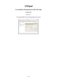
1 Simple Sound Detection circuit . Detecting Sound Students often want to use Sound ' as an input within electronic projects. Unfortunately Sound is not as easy to use as light and temperature, as there is not an instant single component' solution, as is the case with, for example, an LDR for light or a thermistor for temperature. The main problems with Detecting Sound are: 1) electret microphone inserts are low cost, but only produce a very small signal, which requires amplification 2) the background noise level can vary considerably, and so some form of calibration is required 3) some noises, such as a hand-clap, are very quick and so can be missed' with some electronic circuits ( when using a microcontroller). Fortunately these problems can all be overcome at low-cost, by using an electret microphone with three common transistors. The circuit shown in Figure 1 will produce an analogue signal between 0 and 3V that can be detected, for instance, with the analogue input pin of a PIC microcontroller ( Picaxe ).
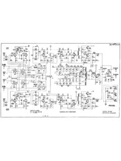
2 The circuit also includes a time-delay' feature that extends the time period of the loudest signal. This means the circuit could also be used, for example, to switch a FET on for a period of time to drive a motor ( in a shop display system). Sound Detection circuit + V. MIN. R1 RV1 RV2 R6. 4k7 100R. 4k7 47k C. SENSITIVITY. MAX. SET ZERO. B. Q3. BC548B. E. B. Q2 E. BC558B. R3 C3 D1. 100k C2 C. OUTPUT. 1n0. 0 to +3 V. ELECTRET C. 470n 1N4148. MICROPHONE C1 Q1 R5 R7 R8. + B BC548B 220k 4k7 C4 10k 470n 470n - E. 0V. The output may be connected to a Picaxe analogue input ( input 1). (readadc 1, b1). or to a Picaxe digital input ( input 2). (if pin2 = 1 then ). QTY PART-REFS VALUE. --- --------- ----- Resistors --------- 2 R1,R7 4k7. 1 R3 100k 1 R5 220k 1 R6 100R. 1 R8 10k Capacitors ---------- 3 C1,C3,C4 470n 1 C2 1n0. Transistors ----------- 2 Q1,Q3 BC548B. 1 Q2 BC558B. Diodes ------ 1 D1 1N4148. Miscellaneous ------------- 1 ELECTRET MICROPHONE.
3 1 RV1 4k7. 1 RV2 47k Operation The circuit shown in Figure 1 can be used in two ways: 1) As an analogue Sound level recorder, for instance connected to the analogue input of a Picaxe microcontroller 2) As a digital on/off switch, for instance connected to the digital input of a Picaxe microcontroller. In the ' Sound level recording' mode, the 'sensitivity' control RV1 is first set to minimum and then the 'set-zero' control RV2 is adjusted for zero output (ie 0V on a multi-meter). In practice is it actually better to be very slightly above zero output to avoid a 'dead band'. The sensitivity' control is now increased to a suitable level for the project. Normal speech at about 50 cm from the microphone will give a DC output of about + 1 V. A handclap will produce a full output of +3 V. The output is instantly high, but slowly decays - so that the signal is present longer than the actual loud noise. The length of time for the decay varies according to the value of C4 (see explanation below) the decay time of the output signal is approximately seconds with the value of C4 as shown.
4 Increasing C4 to uF. provides a decay time of approximately 2 seconds. When a 'digital' on/off output is required, the 'set zero' control, in conjunction with the 'sensitivity' control, are simply used to set a threshold level - where only signals above this level produce an output. Providing that the input signal is high enough, a full 3V. pulse will appear at the output. How does the circuit work? Stage 1 - Electret Microphone A low-cost Electret microphone ( Rapid 35-0192) will provide an output of around 1mV rms from normal speech at a distance of around 60 cm. So you can expect signal levels from the microphone of around 1 - 3 mV. An electret microphone is a special type of Field Effect Transistor (FET), which converts vibrations (from Sound or physical contact) into an electric signal, which is then amplified internally by the FET. The electret is therefore polarised, and must be connected the correct way around - the 0V (negative) leg can be identified as it is connected to the external metal can by a visible tag.
5 Stage 2 Transistor Amplifier The first transistor, Q1, acts as an amplifier providing a gain of x25 (28dB) over the frequency range 300 Hz - 30 kHz, and so will provide an output signal level in the range 25 - 75 mV. The signal level can be adjusted by the 'sensitivity' control RV1. Stage 3 Signal Rectifier Sound is made up of constantly rising and falling waveforms (try looking at the output from a microphone on an oscilloscope). Therefore to detect the highest Sound level you need a reference point, and this circuit therefore only looks at the negative going' part of the waveform. By amplifying the point at which the Sound waveform starts to drop back down again, you can identify the highest point of the Sound level. Therefore the PNP transistor Q2 is biased to cut off, and amplify, only negative-going signals. The resultant positive-going signal, at the collector of Q2, causes D1 to conduct, thus charging C4 to the peak signal voltage.
6 Stage 4 Buffer and Time Delay The third transistor, Q3, is configured as an emitter-follower and buffers the signal (and provides a low output impedance). The circuit provides a fast rise of output voltage with a slower decay, proportional to the value of C4. This basically means that C4 defines the delay time' that the highest Sound level is present for. The decay time of the output signal is approximately seconds with the value of C4 as shown. Increasing C4 to uF provides a decay of approximately 2 seconds. circuit and Text Revolution Education Ltd 2003. All rights reserved.


![[China] Qingdao General OA Supply Co., Ltd.](/cache/preview/8/4/2/c/0/0/7/b/thumb-842c007bc07714900024f84d743a16b1.jpg)


