Transcription of Sinusoidal Control of PMSM Motors with dsPIC30F …
1 AN1017. Sinusoidal Control of PMSM Motors with dsPIC30F DSC. for motor Control : motor Control Pulse Width Modula- Author: Jorge Zambada tion (MCPWM) and high-speed A/D Converter. The Microchip Technology Inc. DSP engine of the dsPIC30F2010 supports the necessary fast mathematical operations. INTRODUCTION The dsPIC30F2010 family member is a 28-pin 16-bit This application note describes a method of driving a DSC specifically designed for low-cost/high efficiency sensored Permanent Magnet Synchronous motor motor Control applications. The dsPIC30F2010.
2 (PMSM) with Sinusoidal currents controlled by a provides these key features: dsPIC30F Digital Signal Controller (DSC). The motor 30 MIPS processing performance Control firmware uses the dsPIC30F peripherals while Six independent or three complementary pairs of the mathematical computations are performed by the dedicated motor Control PWM outputs DSP engine. The firmware is written in C' language, Six-input, 1 Msps ADC with simultaneous sam- with some subroutines in assembly to take advantage pling capability from up to four inputs of the special DSP operations of the dsPIC30F .
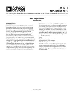
3 Multiple serial communications: UART, I2C and SPI. APPLICATION FEATURES Small package (6 mm x 6 mm QFN) for Sinusoidal current generation for controlling embedded Control applications PMSM motor phases using Space Vector DSP engine for fast response in Control loops Modulation (SVM). Synchronization of Sinusoidal voltages to PMSM HARDWARE REQUIRED. motor position Four-quadrant operation allowing forward, You will need the following hardware to implement the reverse and braking operation described motor Control application: Closed-loop speed regulation using digital PICDEM MCLV Development Board (Figure 1).
4 Proportional Integral Derivative (PID) Control Hurst DMB0224C10002 BLDC motor Phase advance operation for increased speed 24 VDC Power Supply range You can purchase these items from Microchip as a Fractional math operations performed by the DSP complete kit or as individual components. Check the engine of the dsPIC DSC Development Tools section of the Microchip web site for ordering information. motor Control with DIGITAL. SIGNAL CONTROLLERS FIGURE 1: PICDEM MCLV. DEVELOPMENT BOARD. The dsPIC30F motor Control family is specifically designed to Control the most popular types of Motors , including AC Induction Motors (ACIM), Brushed DC.
5 Motors (BDC), Brushless DC Motors (BLDC) and Per- manent Magnet Synchronous Motors (PMSM), to list a few. Several application notes have been published for ACIM operation (AN984, AN908 and GS004) and Brushless DC motor Control operation (AN901, AN957. and AN992) based on the dsPIC30F motor Control fam- ily. These application notes are available on the the Microchip web site ( ). This application note demonstrates how the dsPIC30F2010 is used to Control a sensored PMSM. motor with Sinusoidal voltages. The design takes advantage of dsPIC30F peripherals specifically suited 2005 Microchip Technology Inc.
6 DS01017A-page 1. Sinusoidal Control OF PMSM Motors with dsPIC30F DSC. It is strongly recommended that you read the On the low side, the voltage limit is 10V. On the high PICDEM MCLV Development Board User's Guide side, the voltage limit is 48V. It is important to note that (DS51554) to fully understand the hardware topology the heat sink on the IGBTs have very limited heat dissi- being used in this application note. This User's Guide pation, so high power requirements may not be easily can be downloaded from the Microchip web site. met with the PICDEM MCLV development board.
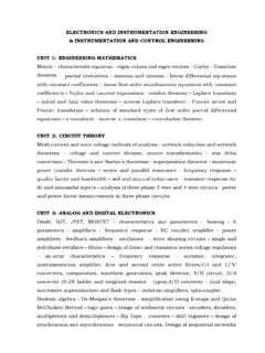
7 Figure 2 is a simplified system block diagram for a To use the PICDEM MCLV development board for this Sinusoidal PMSM motor Control application. This application, use the jumper settings shown in Table 1 and diagram will help you develop your own hardware. the motor connections shown in Table 2 and Table 3. FIGURE 2: SYSTEM BLOCK DIAGRAM TABLE 1: PICDEM MCLV. dsPIC30F2010 DEVELOPMENT BOARD. PWM3H JUMPER SETTINGS. PWM3L Phase A Position for Sinusoidal 3-Phase PWM2H 3-Phase Phase B PMSM Jumpers Control (dsPIC DSC. Inverter PWM2L Phase C.)
8 motor Sensored). PWM1H. J7, J8, J11 Open PWM1L. J12, J13, J14 Open AN1 IBUS. J15, J16, J17, J10 Open R14 R26. AN2 J19 Short Reference Speed S2 +5V TABLE 2: CONNECTIONS FOR motor . RC14. Start/Stop WINDINGS*. R24 R23 R20 Position for Sinusoidal Hall A R21. RB3/CN5 Connector J9 Control (dsPIC DSC. Hall B R22 Sensored). RB4/IC7. RB5/IC8 Hall C R25. M3 Phase A (White). M2 Phase B (Black). Salient aspects of this topology are: M1 Phase C (Red). Potentiometer R14 selects the desired speed G Ground (Green) if available (Reference Speed). Rotor position is detected using Hall effect TABLE 3: motor CONNECTIONS FOR.
9 Sensors connected to pins RB3, RB4 and RB5 HALL SENSORS*. Current feedback is provided through a simple Position for Sinusoidal operational amplifier circuit Connector J9 Control (dsPIC DSC. Fault input is received through a comparator cir- Sensored). cuit connected with the current feedback circuit. +5V Red The current is sensed using a ohm resistor (R26) GND Black You can easily adjust the values of the resistors to HA White accommodate the current capabilities of the motor HB Brown being used for your application. The motor drive circuit, HC Green on the other hand, is designed to drive a 24V PMSM.
10 * The colors referenced in Tables 2 and 3 for motor . You can change the hardware to meet the drive the motor windings and hall sensors, requirement of a specific motor . respectively, pertain to the Hurst 24V motor Note: Refer to the PICDEM MCLV Develop- available from Microchip. The ground wire ment Board User's Guide (DS51554) for is sometimes not available on some details on how to change the hardware for Motors . use with Motors greater or less than 24V. After your code is developed and you have down- loaded it to the dsPIC30F , you will need to press switch S2 to start and stop the motor .