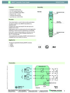
Transcription of SMART Current Driver KFD2-SCD2-Ex1.LK Features Assembly
1 Release date 2017-08-09 14:17 Date of issue to "General Notes Relating to Pepperl+Fuchs Product Information".Pepperl+Fuchs GroupUSA: +1 330 486 0002 Singapore: +65 6779 9091 Germany: +49 621 776 Current DriverZone 0, 1, 2 Div. 1, +IPHART7-8+9+250 mAHART24 V DC14+15-Power Rail24 V DCERRC onnectionAssembly 1-channel isolated barrier 24 V DC supply (Power Rail) Current output up to 700 load HART I/P and valve positioner Line fault detection (LFD) Accuracy % Terminal blocks with test sockets Up to SIL 2 acc. to IEC 61508 FunctionThis isolated barrier is used for intrinsic safety applications. It drives SMART I/P converters, electrical valves, and positioners in hazardous signals are superimposed on the analog values at the field or control side and are transferred transferred across the DC/DC converter is repeated at terminals 1 and open and shorted field circuit presents a high input impedance to the control side to allow line fault detection by control the loop resistance for the digital communication is too low, an internal resistor of 250 between terminals 8 and 9 is available, which may be used as the HART communication for the connection of a HART communicator are integrated into the terminals of the unique collective error messaging feature is available when used with the Power Rail viewLED green:Power supplyRemovable terminalsgreenRemovable terminalblueLED red:LB and SCSwitch S1.
2 HART communicationRelease date 2017-08-09 14:17 Date of issue to "General Notes Relating to Pepperl+Fuchs Product Information".Pepperl+Fuchs GroupUSA: +1 330 486 0002 Singapore: +65 6779 9091 Germany: +49 621 776 specificationsSignal type Analog outputFunctional safety related parametersSafety Integrity Level (SIL) SIL 2 SupplyConnection Power Rail or terminals 14+, 15-Rated voltage Ur20 .. 35 V DCRipple within the supply tolerancePower dissipation W at 20 mA into 10 V (equivalent to 500 ) loadPower consumption 1 W at 20 mAInputConnection side control sideConnection terminals 7-, 8+, (9+)Voltage drop approx. 4 V or internal resistance 200 at 20 mAInput resistance > 100 k , when wiring resistance in the field > 16 V (equivalent to 800 at 20 mA) Current 4 .. 20 mA limited to approx. 25 mAOutputConnection side field sideConnection terminals 1+, 2- Current 4.
3 20 mALoad 100 .. 700 Voltage 14 V at 20 mATransfer characteristicsAccuracy %Deviation After calibration at 20 C (68 F): 10 A incl. non-linearity, calibration, hysteresis, supply and load changesInfluence of ambient temperature 1 A/KRise time < 100 s , 10 .. 90 % step changeGalvanic isolationInput/power supply functional insulation, rated insulation voltage 50 V ACIndicators/settingsDisplay elements LEDsControl elements DIP-switchConfiguration via DIP switchesLabeling space for labeling at the frontDirective conformityElectromagnetic compatibility Directive 2014/30/EU EN 61326-1:2013 (industrial locations)ConformityElectromagnetic compatibility NE 21:2011 Degree of protection IEC 60529:2001 Protection against electrical shock UL 61010-1:2004 Ambient conditionsAmbient temperature -20.
4 60 C (-4 .. 140 F)Mechanical specificationsDegree of protection IP20 Connection screw terminalsMass approx. 150 gDimensions 20 x 124 x 115 mm ( x x inch) , housing type B2 Mounting on 35 mm DIN mounting rail acc. to EN 60715:2001 Data for application in connection with hazardous areasEU-Type Examination Certificate BAS 00 ATEX 7240 Marking II (1)G [Ex ia Ga] IIC , II (1)D [Ex ia Da] IIIC , I (M1) [Ex ia Ma] IOutput [Ex ia Ga] IIC, [Ex ia Da] IIIC, [Ex ia Ma] IVoltage VCurrent Io93 mAPower Po585 mWSupply Maximum safe voltage Um250 V rms (Attention! The rated voltage can be lower.)Input Maximum safe voltage Um250 V rms (Attention!)
5 The rated voltage can be lower.)Certificate T V 99 ATEX 1499 XMarking II 3G Ex nA II T4 [device in zone 2]Galvanic isolation Release date 2017-08-09 14:17 Date of issue to "General Notes Relating to Pepperl+Fuchs Product Information".Pepperl+Fuchs GroupUSA: +1 330 486 0002 Singapore: +65 6779 9091 Germany: +49 621 776 safe electrical isolation acc. to IEC/EN 60079-11, voltage peak value 375 VOutput/power supply safe electrical isolation acc. to IEC/EN 60079-11, voltage peak value 375 VDirective conformity Directive 2014/34/EU EN 60079-0:2012+A11:2013 , EN 60079-11:2012 , EN 60079-15:2010 International approvalsUL approval Control drawing 116-0173 (cULus)IECEx approval IECEx BAS for [Zone 0] [Ex ia] IIC, [Ex iaD], [Ex ia] IGeneral informationSupplementary information Observe the certificates, declarations of conformity, instruction manuals, and manuals where applicable.
6 For information see date 2017-08-09 14:17 Date of issue to "General Notes Relating to Pepperl+Fuchs Product Information".Pepperl+Fuchs GroupUSA: +1 330 486 0002 Singapore: +65 6779 9091 Germany: +49 621 776 monitoring, input characteristicsDuring lead breakage (> 16 V) in the field the input resistance is > 100 k , the field Current is < 1 mA and the red LED is short circuit (< 50 ) in the field the input resistance is approx. 20 k , the input Current and the field Current are approx. 1 mA and the red LED is voltage drop at the Current input (terminals 7-, 8+) is lower than 4 V. Thus, it corresponds to an input resistance of 200 at 20 mA. The AC input impedance corresponds to the load impedance of the SMART functionWhen using positioners, which do not meet the HART standard, set the switches to the 1 position (without SMART function) (see adjustment table).
7 If you are using field devices with high input impedance and a control system with low output impedance, check wheather HART transparency is working necessary, deactivate HART transparency via the DIP switches. If the impedances are combined as described above, you can for example use the device KCD2-SCD-Ex1 feed module KFD2-EB2 The power feed module is used to supply the devices with 24 V DC via the Power Rail. The fuse-protected power feed module can supply up to 150 individual devices depending on the power consumption of the devices. Collective error messages received from the Power Rail activate a galvanically-isolated mechanical Rail UPR-03 The Power Rail UPR-03 is a complete unit consisting of the electrical insert and an aluminium profile rail 35 mm x 15 mm. To make electrical contact, the devices are simply Rail K-DUCT with Power RailThe profile rail K-DUCT is an aluminum profile rail with Power Rail insert and two integral cable ducts for system and field cables.
8 Due to this Assembly no additional cable guides are Rail and Profile Rail must not be fed via the device terminals of the individual devices!Additional otherswitch settingsnon SMARTA ccessories