Transcription of Spectrum Analyzer Updates - W7ZOI
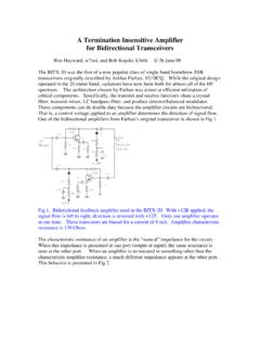
1 Spectrum Analyzer UpdatesLast update , Saturday, June 10, 2000 This part of the web page deals with the Spectrum Analyzer that Terry White (K7 TAU)and I described in QST forAugust and September of 1998, and the related TrackingGenerator appearing in November complete article is now available to be viewed and downloaded inPDF format from ARRL. Go to theARRL web pageand do a search onspectrum Analyzer . This will then get you to a point where the two partpaper can be this photo to see sometutorial info on the Filter for 30 kHz Resolution latest refinement to the Spectrum Analyzer is a narrow filter using monolithic crystalfilter modules from ECS.
2 These readily available parts offer an easy way to get aresolution bandwidth of about 30 kHz, very useful for a variety of applications. (Iroutinely use a 30 kHz RBW for IMD measurements here at W7 ZOI.) This filter is thecollaborative effort of Fred Holler,W2 EKB, and Jack Glandon, first filter, built by Fred, uses a 4 pole filter set, sold as a set in two cans by filter is designed to be terminated in 3 Kat each end. This is realized with inchODferrite transformers using type 61material. This is a relatively low permeabilitymaterial (125)compared with some of the more popular mixes, which means that moreturns are required to achieve the needed inductance.
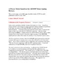
3 (Jack also got good results with-43material, so use what you have.) The 4 pole filter is shown in the following filter elements are NOT symmetrical, so dots indicate the end next to the variablecoupling next figure shows the layout used by Fred on the Kanga IF PC photo below shows two of the filters that Jack built. Shields were tried betweensections, but were not to be needed. The two filters were measured. Then, the two werecascaded and measured again. The results are summarized in the table in kHz for various attenuationvalues in schematicbelow is recommended by ECS when cascading two 4-polesets for an 8pole response.
4 The attenuator is a 6 dB pad with a Z0 of3K has built thistopology and installed it in his Analyzer . He reports a stopband attenuation over 90 thanks to both Fred and Jack fortheir results really lookoutstanding, especially with 8 resonators. Narrow bandwidth is important in determiningresolution. Stopband attenuation should always be at least as much as the on-screendisplay range. Indeed, even higher stopband attenuation is useful, for the Analyzer can beoverdriven in some measurements.(Jan10)Coax Cable Applications in Building the SA and TGAs some of the builders start to get the tracking generator working, we arebeginning tosee a few problems.
5 Some are severe, but they are is important to recognize that the combination of a Spectrum Analyzer and a trackinggenerator is a very difficult thing to build, mainly a result of the extreme shielding andsignal isolation required. The Spectrum Analyzer is a narrow bandwidthreceivercapableof displaying sub microvolt level signals. Yet the tracking generator is atransmitterthatis always generating a signal that is at exactly the same frequency as the sensitivereceiver. With an output of 0 dBm, the TG is at least 100dB higher than the sensitivity ofthe Analyzer , so this is the level of isolation , how do we get there?
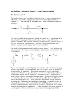
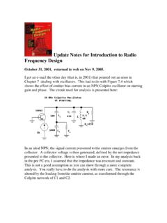
6 Good coax connectors should be used. The SA front-end, theTG, and the SA 2nd LO and mixer should all be in well shielded Hammondboxes (1590B and 1590BB) have worked well for this application and are not terriblyexpensive. All power and control lines in and out of the modules should route throughfeedthrough spite of these precautions, problems have been encountered. Here are some things thatcan help:First, the way the figures were presented in the QST articles lead to confusion. Forexample, Fig. 8 of the August 1998 paper is partially duplicated asthe "before" casebelow. The "Preferred" case is the way we should have shown difference betweenthe two circuits is in the use of coax cable.
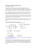
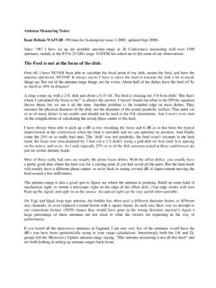
7 Thebeforemerely showed a wire from theedge of the board to the coax connector center pin while thepreferredform emphasizesthatcoaxial cableshould route the signal to the connector. The coax should be groundedat both ends. This wasnotan ARRL drafting error, but a goof on our part in not beingmore careful with our out of the tracking generator or into the SA front end should occur in a wellpreserved coaxial environment. This has to do with the way we get fromthe internalmodules to the edge of the box housing the figure shows the way weoften use a coaxial connector. The connector resides in a hole in the panel. The coaxialcenter wire from, for example the SA low pass filter, attaches to the center of theconnector while the braid is attached to the panel with a solder lug.
8 This is a potentialproblem, a shielding error. There is an open loop. Some signals that are flowing on theinsidesurface of the front panel will be near the connector. These will end upon the samesurfaces that carry the signals that are on their way to the SA low pass filter on the insideof the coax. This constitutes mutual coupling between the two surfaces that willintermingle 's one way to fix the problem:A bulkhead type coaxial connector isnow used to route signals from the "outside world," through the front panel to the coax onthe inside of the Analyzer reaching the circuit modules. A male connector is needed oneach end of the inside cable, adding to expense.
9 Moreover, the bulkhead connector isexpensive. But it is worthwhile. Prior to installing a bulkhead connector in my Analyzer , Icould see a couple of spurious responses from local TV stations. When the bulkheadconnector (Fig. B above) replaced the BNC with solder lug (Fig. A above),the spursdisappeared, even when the lid was off the same effect can be achieved with an extended shield:Here we extend the shield all the way to the front panel. The extension shown in thefigure is rather ideal, for it will come close to preserving the 50 Ohm environment. This snot as vital at low frequencies as is the shielding integrity.
10 It would be suitable, forexample, to push the braid up on the cable, solder the inner connector and insulate it, pullthe shield back down, and clamp a cylinder around coax to the wall. There should ideallybe no gaps in the shield surface such that there is no mutual surface shared by the insideof the coax and the surfaces on the outside. Clearly there is room here for precautions are important for the Analyzer input connections as well as the trackinggenerator output. The integrity of the cable between the VCO and the trackinggeneratoris also thanks to Jack, WB4 RNO for his experimental results with the tracking all of the tracking generators built by hams are the simple ones like we have donefor low frequencies.