Transcription of L CM - W7ZOI Site
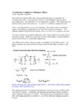
1 An Oscillator Scheme for Quartz Crystal Hayward, 15 Nov07 The familiar quartz crystal is modeled with the circuit shown below containing a seriesinductor LM, capacitor CM, and equivalent series resistor ESR, all paralleled by acapacitor subscript M used with L and C signify that these is a two terminal device, something that has but a single element can becharacterized by studying it with a network analyzer where it is placed between agenerator and a load. The scattering parameters are then measured.
2 Detailed analysis isthen used to extract the four , this is not possible for those of uswithout a basement network analyzer and it is not very can do a simplified analysis with a stable oscillator (usually a VXO) operating as asignal generator with a very low source impedance and a very low load resistance. Thisis shown low source impedance has traditionally been generated with a transformer droppingfrom 50 Ohms down to a source impedance from 3 to 12 are inserted tofurther establish the the impedance is very low, the parallelcapacitance has little impact upon the voltage across the load and can be ignored, at leastfor this simple analysis.
3 Leaving nothing but a series tuned generator istuned to series resonanceto produce a maximum thisagainst a pieceof wire (a through connection to the network analyzer folks) allows the ESR to beinferred from the insertion the generator is then tuned to one side and then tothe other to the 3 dB points, one can measure a loaded Q can then becalculated. Comparison of this value with the inferred ESR plus the source and loadresistance allows the motional inductance to be and the series resonantfrequency yield the motional capacitance, C0, can be measured ata low frequency well removed from an resonance with a simple capacitance some experiments using these methods in a 1982 QST.
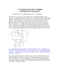
4 (See A UnifiedApproach to the Design of Crystal Ladder Filters, QST, May, 1982.) The scheme hasbeen used in many others who have been building their own crystal filters can be designed with relative ease using traditional methods if weassume the crystals to be nothing more than series tuned filter then takes onthe form shown below where thevariablecapacitors are usually just fixed elementsinserted tomove all meshes to the same frequency, the filter filter uses three sections. Knowing the motional capacitance allows one to calculatethe couplingcapacitors C12and C23for a specified bandwidth, using a normalizedcoupling coefficient for the filter response shape (Butterworth, Chebyshev, etc) that , an end section Q can be calculated from a normalized end sectionQ and the desired bandwidth.
5 Knowledge of this Q and the motional inductance allowsone to pick termination values that will yield the termination , things are not as simple as we might like. The existence of C0with our crystalsimposes is limited to narrow filters if using the so called laddertopology depicted. The bandwidth is of the order of the difference between the seriesand parallel resonant frequencies of the crystals. Even when building filters within theallowed bandwidth limits, the parallel capacitance complicates the Characterization with an OscillatorCrystal ladder filters can be designed if one knows themotionalparameters.
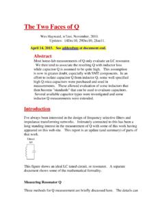
6 Althoughthe network analyzer schemes are ideal, one can also do a good job with a crystaloscillator. Such a circuit is shown in Fig on page ofExperimental Methods inRF circuit is presented in EMRFD with a simple equation for motional C,but nothing is offered in the way of a hint about where the equation originated. That isthe primary goal of this scheme was suggested by G3 UUR in a biasing details, the oscillator is shown in Fig 1 this circuit is in oscillation, the load imposed by the transistor is fairly small andcan be capacitor at the collector is just a bypass of large value and doesnot impact the parallel capacitors shown as Cp are large invalue compared with any of the capacitors in the crystal values might be470 to 1000 is a series capacitor that can be short circuited with a switch.
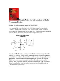
7 Atypical value might be 33 pF. Throwing the switch might produce a 2 kHz shift with a10 MHz includes the parallel capacitance of the open switch, which can beseveral circuit used to calculate resonances from known motional parameters is presented inFig circuit includes the motional elements of the the assumption that the Cpis very large and does not alter resonance, we arriveat Fig the time being,assume that we can neglect the parallel capacitance, C0. This leavesus with the simple circuit of Fig 421 LmCm This figure now includes an equation for the resonant angular frequency, 4, wherethesubscript4 just represents the figure represents the case where the switchof Fig 1 is closed, removing Csfrom the 5 shows the circuitwith the switch CsCm 521 LmCmCs CsCm Two capacitors are in series in this circuit, so theyhave an effective capacitance Ce resulting in a slightly higher angular frequency , the switched capacitance, is known from.
8 We measure thefrequencies of oscillation with a counter. This leave us with two equations for 4and 5in the two unknowns Lmand we subtract one equation from the other we obtain 52 42 1 LmCmCs CsCm 1 LmCm This simplifies tobecome 52 42 1 LmCs or1 LmCs 52 42 But the motional L is related to the angular frequency with the switch closed shown inFig 4 above,1 LmCm 42 This gives us two equations for 1 Lmbetween them yieldsCmCs 52 42 42 orCmCs 52 421 We now redefine the upper frequency as the sum of the lower and a frequency shift,f5f4 f Using this form.
9 And the usual definitions 42 f4 52 f4 f If we substitute these into the expressionfor Cm, we obtainCmCs f 2 f4 f f42 Cs f f42 ff4 There are two terms on the right side. One is just the integer 2 while the other is a ratioof two recall that a typical value for f is 2 kHz for f4=10 MHz. Theratio is much less than 2,so we ignore it, which leavesCm2 Cs ff We have dropped the 4 subscript with the understanding that the crystal seriesresonance is the defining oscillation two oscillator frequencies are soclose to each other that it makesno difference which is chose to ignore C0in this derivation actual circuit is that of Fig 6, is just a redrawing of Fig C0is merely in parallel with , a betterform for the equation would beCm2 CsC0 ff Having motional capacitance.
10 The motional inductance is easily calculated from the seriesresonant capacitance, C0, is easily measured with a lowerfrequency usuallyuse an AADE LC , one can obtain anapproximate value with C0=220 relationship follows from the physics of theAT-Cut quartz crystal, but does not include capacitance of any package that might holdthe a better guess would be C0=220 CM+1 earlier, the simple oscillator scheme for determining motional parameterswas suggested to me in a1982 or 83letter from Dr. David Gordon-Smith, Smith, K8 ZOA, pointed out that I really needed to include parallel capacitance withthe switched capacitance in the formula for motional to both ofthese experimenters.