Transcription of TCS230 PROGRAMMABLE COLOR LIGHT-TO …
1 TCS230 PROGRAMMABLECOLOR LIGHT-TO - frequency CONVERTERTAOS046 - FEBRUARY 20031 The LUMENOLOGY Company Copyright 2003, TAOS High-Resolution Conversion of LightIntensity to frequency PROGRAMMABLE COLOR and Full-Scale OutputFrequency Communicates Directly With a Microcontroller Single-Supply Operation ( V to V) Power Down Feature Nonlinearity Error Typically at 50 kHz Stable 200 ppm/ C Temperature Coefficient Low-Profile Surface-Mount Package DescriptionThe TCS230 PROGRAMMABLE COLOR LIGHT-TO - frequency converter combines configurable silicon photodiodes anda current-to- frequency converter on single monolithic CMOS integrated circuit. The output is a square wave(50% duty cycle) with frequency directly proportional to light intensity (irradiance). The full-scale outputfrequency can be scaled by one of three preset values via two control input pins.
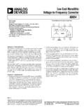
2 Digital inputs and digital outputallow direct interface to a microcontroller or other logic circuitry. Output enable (OE) places the output in thehigh-impedance state for multiple-unit sharing of a microcontroller input LIGHT-TO - frequency converter reads an 8 x 8 array of photodiodes. Sixteen photodiodes have blue filters, 16photodiodes have green filters, 16 photodiodes have red filters, and 16 photodiodes are clear with no four types (colors) of photodiodes are interdigitated to minimize the effect of non-uniformity of incidentirradiance. All 16 photodiodes of the same COLOR are connected in parallel and which type of photodiode thedevice uses during operation is pin-selectable. Photodiodes are 120 m x 120 m in size and are on 144- Block DiagramLightCurrent-to-FrequencyConverte rPhotodiodeArrayS2S3S0S1 OEOutput Texas Advanced Optoelectronic Solutions Jupiter Road, Suite 205 Plano, TX 75074 (972) 673-07598 S37 S26 OUT5 VDDSOIC PACKAGE(TOP VIEW)SO 1S1 2OE 3 GND 4 TCS230 PROGRAMMABLECOLOR LIGHT-TO - frequency CONVERTERTAOS046 - FEBRUARY 20032 Copyright 2003, TAOS LUMENOLOGY supply ground.
3 All voltages are referenced to for fo (active low).OUT6 OOutput frequency (fo).S0, S11, 2 IOutput frequency scaling selection , S37, 8 IPhotodiode type selection voltageTable 1. Selectable OptionsS0S1 OUTPUT frequency SCALING (fo)S2S3 PHOTODIODE TYPELLP ower downLLRedLH2%LHBlueHL20%HLClear (no filter)HH100%HHGreenAvailable OptionsDEVICETAPACKAGE - LEADSPACKAGE DESIGNATORORDERING NUMBERTCS230-25 C to 85 CSOIC-8 DTCS230 DAbsolute Maximum Ratings over operating free-air temperature range (unless otherwise noted) Supply voltage, VDD (see Note 1) 6 V.. Input voltage range, all inputs, VI - V to VDD + V.. Operating free-air temperature range, TA 0 C to 70 C.. Storage temperature range - 25 C to 85 C.. Lead temperature 1,6 mm (1/16 inch) from case for 10 seconds 260 C.. Stresses beyond those listed under absolute maximum ratings may cause permanent damage to the device.
4 These are stress ratings only, andfunctional operation of the device at these or any other conditions beyond those indicated under recommended operating conditions is notimplied. Exposure to absolute-maximum-rated conditions for extended periods may affect device 1: All voltage values are with respect to Operating ConditionsMINNOMMAXUNITS upply voltage, input voltage, VIHVDD = V to V2 VDDVLow-level input voltage, VILVDD = V to free-air temperature range, TA070 CTCS230 PROGRAMMABLECOLOR LIGHT-TO - frequency CONVERTERTAOS046 - FEBRUARY 20033 The LUMENOLOGY Company Copyright 2003, TAOS Characteristics at TA = 25 C, VDD = 5 V (unless otherwise noted)PARAMETERTEST CONDITIONSMINTYPMAXUNITVOHHigh-level output voltageIOH = -4 output voltageIOL = 4 input current5 AIILLow-level input current5 AISupply currentPower-on mode23mAIDDS upply currentPower-down mode715 AS0 = H, S1 = H500600kHzFull-scale frequency (See Note 2)S0 = H, S1 = L100120kHzFull scale frequency (See Note 2)
5 S0 = L, S1 = H1012kHzTemperature coefficient of output frequency 700 nm, -25 C TA 70 C 200ppm/ CkSVSS upply voltage sensitivityVDD = 5 V 10% 2: Full-scale frequency is the maximum operating frequency of the device without LIGHT-TO - frequency CONVERTERTAOS046 - FEBRUARY 20034 Copyright 2003, TAOS LUMENOLOGY Characteristics at VDD = 5 V, TA = 25 C, S0 = H, S1 = H (unless otherwise noted) (See Notes 3, 4, 5, 6, and 7).PARAMETERTEST CONDITIONSCLEARPHOTODIODES2 = H, S3 = LBLUEPHOTODIODES2 = L, S3 = HGREENPHOTODIODES2 = H, S3 = HREDPHOTODIODES2 = L, S3 = LUNITCONDITIONSMINTYPMAXMINTYPMAXMINTYPM AXMINTYPMAXEe = W/cm2, p = 470 = W/cm2, p = 524 = W/cm2, p = 635 nm162024141924kHzEe = 0212212212212Hz p = 470 nm4393608831 RIrradianceresponsivity p = 524 nm51018934746Hz/(W/Reresponsivity(Note 8) p = 565 nm54849318110( W/cm2)(Note 8) p = 635 nm6103037579cm2) p = 470 nm13701670 SaturationIrradiance p = 524 nm11801730 W/Irradiance(Note 9) p = 565 nm10901890 W/cm2(Note 9) p = 635 nm9801040 p = 470 nm58548011741 RIlluminanceresponsivity p = 524 nm9836679Hz/Rvresponsivity(Note 10) p = 565 nm9285318Hz/lx(Note 10) p = 635 nm4072025386fO = 0 to 5 kHz (Note 11)fO = 0 to 50 kHz (Note 11)
6 FO = 0 to 500 kHz powerdown100100100100 sResponsetime to out-put enable(OE)100100100100nsNOTES: 3. Optical measurements are made using small-angle incident radiation from a light -emitting diode (LED) optical The 470 nm input irradiance is supplied by an InGaN light -emitting diode with the following characteristics: peak wavelength p = 470 nm, spectral halfwidth = 35 nm, and luminous efficacy = 75 The 524 nm input irradiance is supplied by an InGaN light -emitting diode with the following characteristics: peak wavelength p = 524 nm, spectral halfwidth = 47 nm, and luminous efficacy = 520 The 565 nm input irradiance is supplied by a GaP light -emitting diode with the following characteristics: peak wavelength p = 565 nm, spectral halfwidth = 28 nm, and luminous efficacy = 595 The 635 nm input irradiance is supplied by a AlInGaP light -emitting diode with the following characteristics: peak wavelength p = 635 nm, spectral halfwidth = 17 nm, and luminous efficacy = 150 Irradiance responsivity Re is characterized over the range from zero to 5 Saturation irradiance = (full-scale frequency )/(irradiance responsivity).
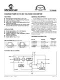
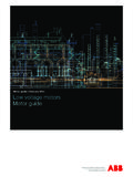
7 10. Illuminance responsivity Rv is calculated from the irradiance responsivity by using the LED luminous efficacy values stated in notes4, 5, and 6 and using 1 lx = 1 Nonlinearity is defined as the deviation of fO from a straight line between zero and full scale, expressed as a percent of full LIGHT-TO - frequency CONVERTERTAOS046 - FEBRUARY 20035 The LUMENOLOGY Company Copyright 2003, TAOS CHARACTERISTICSF igure 1300500700900 Relative Responsivity1100 - Wavelength - nmTA = 25 CPHOTODIODE SPECTRAL toClear@ 680 nmRedClearGreenBlueFigure 2300500700900 Relative Responsivity1100 - Wavelength - nmTA = 25 CPHOTODIODE SPECTRAL RESPONSIVITY WITHEXTERNAL HOYA CM500 toClear@ 530 nmClearGreenRedBlueTCS230 PROGRAMMABLECOLOR LIGHT-TO - frequency CONVERTERTAOS046 - FEBRUARY 20036 Copyright 2003.
8 TAOS LUMENOLOGY INFORMATIONP ower supply considerationsPower-supply lines must be decoupled by a F to F capacitor with short leads mounted close to thedevice interfaceA low-impedance electrical connection between the device OE pin and the device GND pin is required forimproved noise interfaceThe output of the device is designed to drive a standard TTL or CMOS logic input over short distances. If linesgreater than 12 inches are used on the output, a buffer or line driver is type ( COLOR ) selectionThe type of photodiode (blue, green, red, or clear) used by the device is controlled by two logic inputs, S2 andS3 (see Table 1).Output frequency scalingOutput- frequency scaling is controlled by two logic inputs, S0 and S1. The internal LIGHT-TO - frequency convertergenerates a fixed-pulsewidth pulse train.
9 Scaling is accomplished by internally connecting the pulse-train outputof the converter to a series of frequency dividers. Divided outputs are 50%-duty cycle square waves with relativefrequency values of 100%, 20%, and 2%. Because division of the output frequency is accomplished by countingpulses of the principal internal frequency , the final-output period represents an average of the multiple periodsof the principle output-scaling counter registers are cleared upon the next pulse of the principal frequency after anytransition of the S0, S1, S2, S3, and OE lines. The output goes high upon the next subsequent pulse of theprincipal frequency , beginning a new valid period. This minimizes the time delay between a change on the inputlines and the resulting new output period. The response time to an input programming change or to an irradiancestep change is one period of new frequency plus 1 S.
10 The scaled output changes both the full-scale frequencyand the dark frequency by the selected scale frequency -scaling function allows the output range to be optimized for a variety of measurementtechniques. The scaled-down outputs may be used where only a slower frequency counter is available, suchas low-cost microcontroller, or where period measurement techniques are the frequencyThe choice of interface and measurement technique depends on the desired resolution and data acquisitionrate. For maximum data-acquisition rate, period-measurement techniques are data can be collected at a rate of twice the output frequency or one data point every microsecond forfull-scale output. Period measurement requires the use of a fast reference clock with available resolution directlyrelated to reference clock rate.