Transcription of KIT TC7662B CHARGE PUMP DC-TO-DC VOLTAGE …
1 TC7662 BTC7662B-8 9/11/96 EVALUATIONKITAVAILABLE 2001 Microchip Technology Inc. DS21469 ACHARGE PUMP DC-TO-DC VOLTAGE CONVERTERFEATURES Wide Operating VOLTAGE Range: to 15V Boost Pin (Pin 1) for Higher Switching Frequency High Power Efficiency is 96% Easy to Use Requires Only 2 External Non-CriticalPassive Components Improved Direct Replacement for Industry Stan-dard ICL7660 and Other Second Source DevicesAPPLICATIONS Simple Conversion of +5V to 5V Supplies VOLTAGE Multiplication VOUT = nVIN Negative Supplies for Data Acquisition Systemsand Instrumentation RS232 Power Supplies Supply Splitter, VOUT = VS/2 GENERAL DESCRIPTIONThe TC7662B is a pin-compatible upgrade to the Indus-try standard TC7660 CHARGE pump VOLTAGE converter . Itconverts a + to +15V input to a corresponding to 15V output using only two low-cost capacitors, eliminatinginductors and their associated cost, size and on-board oscillator operates at a nominal fre-quency of 10kHz.
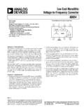
2 Frequency is increased to 35kHz whenpin 1 is connected to V+, allowing the use of smaller externalcapacitors. Operation below 10kHz (for lower supply currentapplications) is also possible by connecting an externalcapacitor from OSC to ground (with pin 1 open).The TC7662B is available in both 8-pin DIP and 8-pinsmall outline (SO) packages in commercial and extendedtemperature BLOCK DIAGRAMTC7662 BGNDINTERNALVOLTAGEREGULATORRCOSCILLATOR VOLTAGE LEVELTRANSLATOR 2V+CAP+8276 OSCLV3 LOGICNETWORKVOUT5 CAP 41 BOOST12348765TC7662 BCPATC7662 BEPABOOSTCAP+GNDCAP VOUTLOWVOLTAGE (LV)OSC+V12348765TC7662 BCOATC7662 BEOABOOSTCAP+GNDCAP VOUTLOWVOLTAGE (LV)OSC+VPIN CONFIGURATION (DIP AND SOIC)ORDERING INFORMATIONT emperaturePart SOIC0 C to +70 CTC7662 BCPA8-Pin Plastic DIP0 C to +70 CTC7662 BEOA8-Pin SOIC 40 C to +85 CTC7662 BEPA8-Pin Plastic DIP 40 C to +85 CTC7660 EVEvaluation Kit forCharge Pump Family2TC7662 BCHARGE PUMP DC-TO-DCVOLTAGE CONVERTERTC7662B-8 9/11/96 2001 Microchip Technology Inc.
3 DS21469 AELECTRICAL CHARACTERISTICS:V+ = 5V, TA = +25 C, OSC = Free running, Test Circuit Figure 2, UnlessOtherwise ConditionsMinTypMaxUnitI+Supply Current (Note 3)RL = , +25 C 80160 A(Boost pin OPEN OR GND)0 C TA +70 C 180 A 40 C TA +85 C 180 A 55 C TA +125 C 200 AI+Supply Current0 C TA +70 C 300 A(Boost pin = V+) 40 C TA +85 C350 55 C TA +125 C400V+HSupply VOLTAGE Range, HighRL = 10 k , LV Open, TMIN TA 15V(Note 4)V+LSupply VOLTAGE Range, LowRL = 10 k , LV to GND, TMIN TA Source ResistanceIOUT = 20mA, 0 C TA +70 C 65100 IOUT = 20mA, 40 C TA +85 C 120 IOUT = 20mA, 55 C TA +125 C 150 IOUT = 3mA, V+ = 2V, LV to GND , 250 0 C TA +70 CIOUT = 3mA, V+ = 2V, LV to GND , 300 40 C TA +85 CIOUT = 3mA, V+ = 2V, LV to GND , 400 55 C TA +125 CfOSCO scillator FrequencyCOSC = 0,Pin 1 Open or GND510 kHzPin 1 = V+35 PEffPower EfficiencyRL = 5k 9696 %TMIN TA TMAX9597 VOUTEffVoltage Conversion EfficiencyRL = %ZOSCO scillator ImpedanceV+ = 2V 1 M V+ = 5V 100 k NOTES:1.
4 Connecting any terminal to voltages greater than V+ or less than GND may cause destructive latch-up. It is recommended that no inputs fromsources operating from external supplies be applied prior to power up of the Derate linearly above 50 C by mW/ In the test circuit, there is no external capacitor applied to pin 7. However, when the device is plugged into a test socket, there is usually a verysmall but finite stray capacitance present, of the order of The TC7662B can operate without an external diode over the full temperature and VOLTAGE range. This device will function in existing designs whichincorporate an external diode with no degradation in overall circuit MAXIMUM RATINGS*Supply VOLTAGE .. + , Boost and OSC Inputs VOLTAGE (Note 1)V+< .. to (V+ + )> .. (V+ ) to (V+ + )Current Into LV (Note 1)V+ > .. 20 AOutput Short Duration(VSUPPLY ).
5 ContinuousPower Dissipation (TA 70 C) (Note 2)Plastic DIP .. 730mWSO .. 470mWOperating Temperature RangeC Suffix .. 0 C to +70 CE Suffix .. 40 C to +85 CStorage Temperature Range .. 65 C to +150 CLead Temperature (Soldering, 10 sec) .. +300 C* Static-sensitive device. Unused devices must be stored in conductivematerial. Protect devices from static discharge and static fields. Stressesabove those listed under "Absolute Maximum Ratings" may cause perma-nent damage to the device. These are stress ratings only and functionaloperation of the device at these or any other conditions above thoseindicated in the operation sections of the specifications is not to absolute maximum rating conditions for extended periodsmay affect device PUMP DC-TO-DCVOLTAGE CONVERTERTC7662B-8 9/11/96 2001 Microchip Technology Inc.
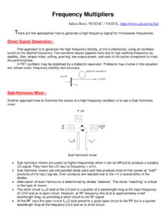
6 DS21469 AFigure 2. Idealized Negative VOLTAGE CapacitorTHEORETICAL POWER EFFICIENCYCONSIDERATIONSIn theory, a VOLTAGE converter can approach 100%efficiency if certain conditions are met:A. The drive circuitry consumes minimal The output switches have extremely low ON resistanceand virtually no The impedances of the pump and reservoir capacitorsare negligible at the pump TC7662B approaches these conditions for nega-tive VOLTAGE conversion if large values of C1 and C2 are is lost only in the transfer of CHARGE betweencapacitors if a change in VOLTAGE occurs. The energy lostis defined by:E = 1/2 C1 (V12 V22)where V1 and V2 are the voltages on C1 during the pump andtransfer cycles. If the impedances of C1 and C2 are relativelyhigh at the pump frequency (refer to Figure 2) compared tothe value of RL, there will be a substantial difference involtages V1 and V2.
7 Therefore, it is desirable not only tomake C2 as large as possible to eliminate output voltageripple, but also to employ a correspondingly large value forC1 in order to achieve maximum efficiency of and Don ts1. Do not exceed maximum supply Do not connect the LV terminal to GND for supplyvoltages greater than Do not short circuit the output to V+ supply for voltagesabove volts for extended periods; however,transient conditions including start-up are DESCRIPTIONThe TC7662B contains all the necessary circuitry tocomplete a negative VOLTAGE converter , with the exception oftwo external capacitors which may be inexpensive 1 Fpolarized electrolytic types. The mode of operation of thedevice may be best understood by considering Figure 2,which shows an idealized negative VOLTAGE converter . Ca-pacitor C1 is charged to a VOLTAGE V+ for the half cycle whenswitches S1 and S3 are closed.
8 (Note: Switches S2 and S4are open during this half cycle.) During the second half cycleof operation, switches S2 and S4 are closed, with S1 and S3open, thereby shifting capacitor C1 negatively by V+ is then transferred from C1 to C2 such that thevoltage on C2 is exactly V+, assuming ideal switches and noload on C2. The TC7662B approaches this ideal situationmore closely than existing non-mechanical the TC7662B , the four switches of Figure 2 are MOSpower switches; S1 is a P-channel device and S2, S3 and S4are N-channel devices. The main difficulty with this ap-proach is that in integrating the switches, the substrates ofS3 and S4 must always remain reverse biased with respectto their sources, but not so much as to degrade their ON resistances. In addition, at circuit start up, and under outputshort circuit conditions (VOUT = V+), the output VOLTAGE mustbe sensed and the substrate bias adjusted to accomplish this would result in high power lossesand probable device problem is eliminated in the TC7662B by a logicnetwork which senses the output VOLTAGE (VOUT) togetherwith the level translators, and switches the substrates of S3and S4 to the correct level to maintain necessary VOLTAGE regulator portion of the TC7662B is anintegral part of the anti-latchup circuitry; however, its inher-ent VOLTAGE drop can degrade operation at low , to improve low VOLTAGE operation, the LV pinshould be connected to GND, disabling the regulator.
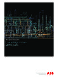
9 Forsupply voltages greater than volts, the LV terminal mustbe left open to insure latchup proof operation and preventdevice 1. TC7662B Test Circuit12348765TC7662B+V+(+5V)V+VOC110 F+C210 FILRLNOTE: For large values of COSC (>1000 pF), the values of C1 and C2 should be increased to 100 = VINC14TC7662 BCHARGE PUMP DC-TO-DCVOLTAGE CONVERTERTC7662B-8 9/11/96 2001 Microchip Technology Inc. DS21469A4. When using polarized capacitors in the inverting mode,the + terminal of C1 must be connected to pin 2 of theTC7662B and the terminal of C2 must be connectedto If the VOLTAGE supply driving the TC7662B has a largesource impedance (25-30 ohms), then a F capaci-tor from pin 8 to ground may be required to limit therate of rise of the input VOLTAGE to less than 2V/ APPLICATIONSS imple Negative VOLTAGE ConverterThe majority of applications will undoubtedly utilize theTC7662B for generation of negative supply voltages.
10 Figure3 shows typical connections to provide a negative supplywhere a positive supply of + to +15V is available. Keepin mind that pin 6 (LV) is tied to the supply negative (GND)for supply voltages below output characteristics of the circuit in Figure 3 canbe approximated by an ideal VOLTAGE source in series with aresistance as shown in Figure 3b. The VOLTAGE source has avalue of (V+). The output impedance (RO) is a function ofthe ON resistance of the internal MOS switches (shown inFigure 2), the switching frequency, the value of C1 and C2,and the ESR (equivalent series resistance) of C1 and C2. Agood first order approximation for RO is:RO 2(RSW1 + RSW3 + ESRC1) + 2(RSW2 + RSW4 +ESRC1) + + ESRC2(fPUMP = , RSWX = MOSFET switch resistance)Combining the four RSWX terms as RSW, we see that:RO 2 x RSW + + 4 x ESRC1 + ESRC2 RSW, the total switch resistance, is a function of supply1fPUMP x C1fOSC21fPUMP x C1t2t1 BAV (V+)0 Figure 4.